ARMY TM 9-2815-252-24
AIR FORCE TO 38G1-92-2
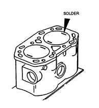
FIGURE 3-30. Checking Cylinder Head Clearance
(5) Remove cylinder head and measure the thickness of solder. This should be 0.0276 to 0.0354 in. (0.7 to
0.9 mm) and is obtained by a single gasket under head.
3-27.4. Repair.
a. Using valve guide replacement tool (317-50033), refer to FIGURE 3-29; remove each valve guide as follows:
(1) Place cylinder head on its side in a soft-jawed vice.
(2) Screw mandrel (1) into tool (2).
(3) Place sleeve (3) onto tool.
(4) Fit bevelled adapter (4) into sleeve (3) and locate bevel into valve seat.
(5) Locate mandrel (1) through guide from valve seat side.
(6) Screw small threaded sleeve (5) onto mandrel (1) at valve rocker side.
(7) Holding sliding handle firmly to prevent rotation, turn double handled lever clockwise until guide is
withdrawn through head.
(8) If it is found difficult to start moving guides a sharp tap with a copper hammer should break seal.
b. Regrind valves and valve seats in cylinder head.
NOTE
Valves seat grinding angles are: 150, 44.5°, and 60°. Valve angle is 45°.
c. Using valve guide removal and replacement tool (317-50033), refer to FIGURE 3-29; install each valve guide.
(1) Install mandrel (1) into valve guide hole from valve rocker end.
(2) Place valve guide over mandrel (1) with counterbored end of guide facing towards valve seats.
(3) Place depth stop (317-50108) (6) over mandrel (1) and screw on threaded sleeve (5).
(4) Fit tool complete with bevelled adapter (4) onto mandrel (1) at valve seat side.
(5) Hold sliding handle firmly to prevent rotating. Turn double handled lever clockwise until depth stop
prevents further movement. At this point guide will protrude 0.463 to 0.482 in. (11.75 to 12.25 mm)
above cylinder head.
3-27.5. Assembly.
3-59
|
|