ARMY TM 9-2815-253-24
AIR FORCE TO 38G1-93-2
MARINE CORPS TM 2815-24/3
3-30.3. Repair.
NOTE
Lay piston rings (6, FIGURE 3-36) out in order of removal to aid in installation.
a. Use a standard ring expander to remove piston rings (6).
b. Remove retaining rings (7) and push pin (8) out of connecting rod (3) and piston (5). Separate piston (5) from
connecting rod (3).
c.
If necessary, replace bushing (9) from connecting rod (3).
d. Install piston (5) to connecting rod (3)with wording CAMSHAFT SIDE on top of piston to same side as
identification marks on connecting rod big end and cap.
e. Insert piston pin (8) and secure with two retaining rings (7).
f.
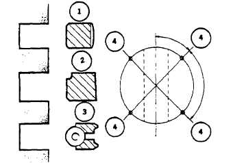
Use a piston ring expander and install piston rings (6) with word TOP facing up as follows. Refer to FIGURE 3-
37:
(1)
Lower groove-oil control ring.
(2)
Middle groove-compression ring.
(3)
Top groove - firing ring.
FIGURE 3-37. Piston Ring and Gap Location
3-30.4. Installation.
a. Turn crankshaft journal to TDC.
NOTE
If necessary, separate each bearing cap (2, FIGURE 3-36) and connecting rod (3) as it is installed.
Do not mix bearing caps and connecting rods.
b. If damaged, install new connecting rod big end bearing shells (4, FIGURE 3-36) ensuring they are correctly
located in both connecting rod and cap.
c.
Stagger piston ring (6) gaps so each ring gap is set at 90 degrees to adjacent rings and 45 degrees from piston
pin (8) axis.
d. Submerge piston and piston rings in dean engine lubricating oil (MIL-L-2104).
e. Fit piston and rod into cylinder while compressing piston rings using a suitable piston ring compressor.
f.
Push down on piston crown and turn crankshaft counterclockwise until big end is almost at Bottom Dead Center
(BDC).
3-64
|
|