ARMY TM 9-2815-253-24
AIR FORCE TO 38G1-93-2
MARINE CORPS TM 2815-24/3
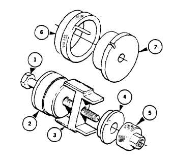
FIGURE 3-41. Main Bearing Tool
3-32.2. Installation.
a.
Install bearing (7, FIGURE 3-40) in main bearing housing (3) as follows:
(1)
Mount housing (3) in a soft-jawed vice with small oil feed hole facing up.
(2)
Place large tapered collar of main bearing tool (317-50111) on a bench with pilot facing up.
(3)
Place new bearing shells (7) into collar ensuring one oil feed hole is in line with pilot pin of collar and end
of shell is in line with the mark on collar face.
(4)
Place driver onto collar with cutout on driver located over collar pilot pin.
(5)
Push driver sufficiently until bearings (7) come out other side of collar to provide a lead in.
(6)
Install assembly into housing (3) from oil seal side (crankcase outside face) with pilot pin in line with oil
feed hole in housing.
(7)
Place bolt through assembly.
(8)
Install bridge, spacer, and nut onto bolt.
(9)
Tighten nut until driver is against face of collar.
(10)
Remove tool.
(11)
Check that oil hole in bearing shell (7) is correctly aligned with oil feed hole in housing (3).
b.
Lightly grease steel back of thrust bearing (5) with general purpose grease (630AA) and position it in housing (3).
Ensure that tab is correctly located and copper face will be toward crankshaft.
c.
Coat both sides of a new main bearing housing shim (4) with sealing compound (MIL-R-46082). Install it to
housing (3) with flat side towards crankcase.
NOTE
Two sizes of shim (4) are available; 0.015 and 0.020 in. (0.38 and 0.5 mm). Start with smaller
shim and check end play.
3-68
|
|