ARMY TM 9-2815-254-24
AIR FORCE TO 38G1-94-2
NOTE
Back end of shaft (18) is the end with the oil supply hole.
e . Install retaining ring (9) and washer (10) on one end of shaft (18). This will be back end of shaft (in relation
to engine).
f.
Installone rocker arm (12), three rocker arms (14) three rocker arms (16), one rocker arm (17), four retaining
plates (13) and three springs (15) following the sequence shown in FIGURES 3-52 and 3-53. Start with rocker
arm (12) and finish with rocker arm (17) (front of engine). Retaining plates are marked with an ‘F and this
side must face the front of engine.
g. Install washer (10) and retaining ring (9) on end of shaft (18)
3-26.5. Installation.
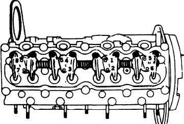
a. Position rocker arm assembly on cylinder head and secure four retaining plates (13, FIGURE 3-52) with two
bolts (7) and washers (8) each. Tighten bolts to 168 in-lbs (19.0 Nm) in sequence shown in FIGURE 3-58.
FIGURE 3-58. Rocker Arm Retaining Plate Bolt Tightening Sequence
3-108
|
|