ARMY TM 9-2815-254-24
AIR FORCE TO 38G1-94-2
(4) Standard clearance between bearing ID and crankpin (step e) is 0.0007 to 0.0025 in. (0.018 to 0.065 mm),
with a limit of 0.0047 in. (0.12 mm)
(5) If clearance exceeds limit, replace bearings and/or crankshaft.
h.
Check crankshaft journal and bearing clearance using bearing gage (PLASTIGAGEPRl) as follows:
(1) Clean cylinder block, journal bearing surfaces, bearing caps, and bearings.
(2) Install bearings in cylinder block.
(3) Carefully place crankshaft on bearings.
(4) Rotate crankshaft approximately 30 degrees to seat bearings.
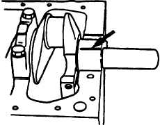
(5) Place bearing gage over crankshaft journal across full width of bearing, refer to FIGURE 3-90.
N O T E
Do not allow crankshaft to turn during bearing cap installation and tight-
ening.
(6) Install bearing caps with bearings. Tighten bearing cap bolts to 123 ft-lbs (166.8 Nm).
(7) Remove bearing caps.
FIGURE 3-90. Crankshaft Joumal and Bearing Clearance
3-139
|
|