ARMY TM 9-2815-254-24
AIR FORCE TO 36G1-94-2
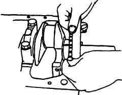
(8) Compare width of bearing gage attached to either crankshaft or bearing against scale printed on bearing
gage container, refer to FIGURE 3-91.
(9) Standard clearance is 0.0007 to 0.0025 in. (0.018 to 0.065 mm), with a limit of 0.0047 in. (0.12 mm).
(10) lf measured clearance exceeds limit, perform clearance check in accordance with step f.
FlGURE 3-91. Comparing Bearing Gage
i.
Check crankpin and bearing clearance using bearing gage (PLASTIGAGEPR1) as follows:
(1) Clean crankshaft, connecting rods, bearing cap, and bearings.
(2) Install bearing to connecting rod and bearing cap.
(3) Prevent connecting rod from moving.
(4) Apply engine lubricating oil (MIL-L-2104) to bearing gage to keep it from falling off and attach bearing
gage to crankpin.
N O T E
Do not allow connecting rod and crankshaft to move when installing and
tightening bearing cap.
(5) Install bearing cap and tighten bolts to 61.5 ft-bs (83.3 Nm).
3-140
|
|