ARMY TM 9-2815-254-24
AIR FORCE TO 38G1-94-2
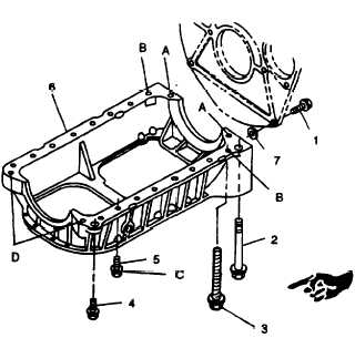
A - 100 mm bolt
B - 120 mm bolt / lockwasher
C - 22 mm screw
D - 45 mm bolt
FIGURE 3-98. Crankcase
3-29.3. Installation.
a.
Apply a coat of sealing compound (FORMGASKET2) to engine block mating surface and to No.
1 and No. 5 bearing cap arch gaskets.
b.
Position crankcase (6, FIGURE 3-98) on engine block, aligning dowel pin in block with hole in
crankcase.
Secure crankcase to engine block with fourteen screws (5) two bolts (2) two bolts (3)
and two screws (4).
c.
Install two shims (7) and two screws (1) securing crankcase to flywheel housing.
d.
Tighten all fasteners a little at a time and in sequence shown in FIGURE 3-99 to 168 in-lbs
(19.0 Nm).
e.
Install oil pan, refer to paragraph 3-17.3.
Change 2 3-149
|
|