ARMY TM 9-2815-254-24
AIR FORCE TO 38G1-94-2
N O T E
Refer to FIGURE D-1, Appendix D to manufacture tappet holders.
n.
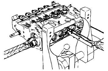
Hold tappet (23, FIGURE 3-8) with clamp (157931-6120). Align tappet guide with pump housing guide groove
and insert tappet (23) and spacer ring (26) through camshaft opening, refer to FIGURE 3-30.
FIGURE 3-30. Inserting Tappet
o.
Using tappet installer (157921-0120) through bottom plug hole, push tappet (23, FIGURE 3-8) upwards, align-
ing plunger flange with groove of cylinder sleeve (29).
p.
When, by pushing upward on tappet (23), plunger (24) is completely inserted into plunger barrel (37) and cylin-
der sleeve (29); insert tappet holder (FIGURE D-1, Appendix D) into small hole on tappet (23) body.
q.
If removed, install rings (22), shims (21), and bearings (20) on each end of camshaft (18).
N O T E
Code number (camshaft assembly mark) will be located on one end of
camshaft indicating governor end.
3-52
|
|