|
|
|
|

|
ARMY TM 9-2815-254-24
AIR FORCE TO 38G1-94-2
g.
Connect fuel pipes and injection pipes. Refer to TABLE 3-2 for correct sizes.
h.
Plug feed pump opening with plastic plug. Fill camshaft chamber with engine lubricating oil (MIL-L-2104) (80
cc). Fill governor chamber with engine oil, refer to PMCS chart (TABLE 3-1).
i.
Remove control rack cap and attach measuring device (105782-6280).
j.
Remove control rack guide screw (38) and lock control lever rack at 0.472 in. (12 mm) using locking screw.
k.
Attach measuring device (105782-4020) to pump housing No. 2 cylinder. Measuring needle must rest on tap-
pet guide pin.
l.
Place No. 2 cylinder cam in bottom dead center (BDC) position. Set dial gage indicator to zero (0).
NOTE
Manually rotate camshaft by hand and ensure that indication of dial
gage indicator varies with change in cam lift.
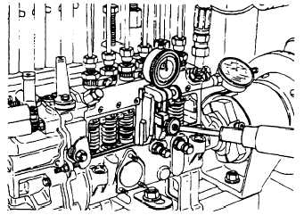
FIGURE 3-31. Measuring Device Installed (Typical)
m. Supply test oil to injection pump at as low a pressure as possible (2.8 psi (19.6 kPa)
3-55
|
|
|
|
|
Privacy Statement -
Copyright Information. -
Contact Us