ARMY TM 9-2815-255-24
AIR FORCE TO 38G1-95-2
MARINE CORPS TM 2815-24/4
CAUTION
Excessive tightening of screw (32) can cause seizure of hydraulic head and rotor assembly.
Insufficient torque may cause leaking and hard starting.
d.
Install delivery valve spring (34) and new delivery valve stop (33) in rotor bore. Using hex end of extractor
(13383), install screw (32). Tighten screw 85 to 90 in-lbs (9.5 to 10 Nm).
e.
If removed, install four new fuel connectors (36) in head. Tighten them 58 to 66 ft-lbs. (78.6 to 89.5 Nm).
f.
Remove rotor from weight cage and submerge it in clean calibrating oil.
CAUTION
Do not force plungers Into bore. Never attempt to press a roller Into a shoe from outer edges, as
groove width at this point Is less than roller outside diameter and shoe breakage can result.
NOTE
If replacing hydraulic head and rotor, or if replacing leaf springs do steps n thru s.
g.
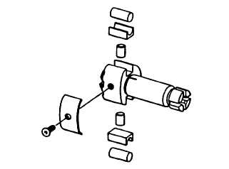
Install two leaf springs (26, FIGURE 3-52) on rotor. Secure with two screws (25).
h.
If removed, install new plungers (29) in their bores and check for freedom of movement. Install two shoes (28)
and rollers (27) on rotor, refer to FIGURE 3-73.
FIGURE 3-73. Installing Rollers and Shoes (Typical)
i.
Carefully handle rotor, holding rollers, and shoes in their slots, and install rotor assembly in fixture (19969) on air
inlet side.
Warning
Compressed air can be hazardous when not used properly.
3-102
|
|