ARMY TM 9-2815-255-24
AIR FORCE TO 38G1-95-2
MARINE CORPS TM 2815-24/4
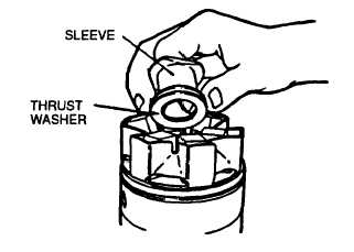
FIGURE 3-77. Installing Thrust Washer and Sleeve
al.
Apply a light film of clean general purpose grease (630AA) to preformed packing (21, FIGURE 3-52) and install
in groove in hydraulic head.
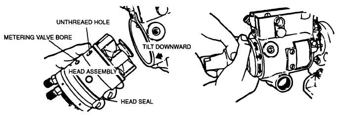
am.
Apply a light film of general purpose grease (630AA) around inside edge of housing and tilt housing slightly
downward at rear to aid in assembly.
an.
Rotate cam ring (24) so threaded hole is in line with metering valve bore. This ensures proper position of cam.
CAUTION
Exercise care not to Insert head assembly too far into housing. Pushing head in too far will
damage seal on hydraulic head and result in leakage. Ensure timing mark on drive corresponds
with timing mark on rotor.
ao.
Grasp hydraulic head firmly in both hands and insert it into housing bore with a slight rotary motion. Do not
force. If assembly should jam during insertion, withdraw and start over, refer to FIGURE 3-78.
FIGURE 3-78. Inserting Hydraulic Head (Typical)
ap.
Rotate head assembly until head locking bolt holes line up with their corresponding holes in housing. Insert two
locking bolts (51, FIGURE 3-45) finger tight.
3-107
|
|