ARMY TM 9-2815-255-24
AIR FORCE TO 38G1-95-2
MARINE CORPS TM 2815-24/4
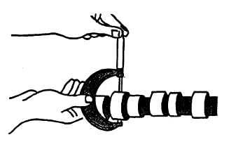
FIGURE 3-111. Measuring Camshaft Journals
e.
Measure camshaft lobe height as follows:
(1)
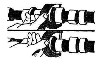
Measure each camshaft lobe at highest point and at narrowest point, refer to FIGURE 3-112. Subtract
narrowest dimension from highest dimension to find camshaft lobe height. If height is not correct on any
lobe, install a new camshaft.
(2)
Intake lobe should be 0.273 to 0.292 inch (6.93 to 7.42 mm), with a minimum acceptable lobe height of
0.263 inch (6.68 mm).
(3)
Exhaust lobe should be 0.266 to 0.286 inch (6.76 to 7.26 mm), with a minimum acceptable lobe height of
0.256 inch (6.50 mm)
FIGURE 3-112. Measuring Camshaft Lobe Height
f.
Inspect cam followers in accordance with instructions in paragraph 3-34.4.
3-40.3. Installation.
a.
Install gear (5, FIGURE 3-108) as follows:
(1)
Install key (6) in camshaft.
(2)
Install gear (5) with timing mark facing away from camshaft (3), aligning slot in gear with key (6).
(3)
Using a tubular driver, press gear (5) on camshaft (3) until gear is flush with shoulder on camshaft.
b.
Coat camshaft lobes and cam followers (2) with a general purpose grease (630AA).
c.
Make sure engine is at TDC, (No. 1 piston on compression stroke) with timing pin engaged in flywheel.
3-162
|
|