ARMY TM 9-2815-255-24
AIR FORCE TO 38G1-95-2
MARINE CORPS TM 2815-24/4
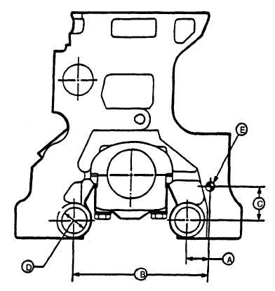
FIGURE 3-114. Balancer Shaft Bushing Line Boring References
d.
Apply a liberal amount of clean engine lubricating oil (MIL-L-2104) to bushings (16) in engine block and to
balancer shaft (13 and 14) journals.
CAUTION
Do not intermix shafts (13 and 14) or gears (11 and 12) in location from which they were removed.
Shafts are lapped for one direction of rotation, and exchanging locations could cause premature
wear of shafts and bushings. If doubt exists as to which shaft Is left or right-hand, always
replace the balancer shaft bushings (16).
e.
Install balancer shafts (13 and 14) and thrust plates (9 and 10).
t.
Secure each thrust plate (9 and 10) with two capscrews (7) and new lockwashers (8). Tighten capscrews to 35 ft-
lbs (47 Nm).
g.
Time balancer shafts as follows:
(1)
Turn right (camshaft side) balancer shaft (14) so timing mark is under timing tool (JD-254). Timing mark
on both balancer shaft gears (11 and 12) must align with centerline of crankshaft when correctly timed.
(2)
Install lower idler gear, and without turning balancer shaft, secure gear. Spring pin must enter hole in
washer when it is installed.
(3)
Install new bolt with washer from oil pump side and new nut on front plate gear side. Secure nut with
adhesive (LOCTITE 242) and tighten to 70 ft-lbs (95 Nm). Stake nut to capscrew by applying three center
punch marks.
3-166
|
|