ARMY TM 9-2815-255-24
AIR FORCE TO 38G1-95-2
MARINE CORPS TM 2815-24/4
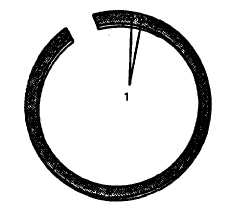
FIGURE 3-145. Compression Ring Identification Marks
(4)
Position gap in rectangular compression ring on opposite side of piston from oil control ring gap.
(5)
Keystone compression ring has a mark to identify top side of ring. Install keystone compression ring in top
ring groove with mark toward top of piston.
(6)
Position gap in keystone compression ring on opposite side of piston from rectangular compression ring
gap.
3-49.2. Cylinder Block.
a.
If removed, install oil galley and water galley plugs, refer to FIGURE 3-127.
b.
Install piston cooling nozzles, refer to FIGURE 3-136, and tighten to 84 in-lbs (9.5 Nm).
c.
Install cylinder liners, refer to paragraph 3-50.2.
d.
Install crankshaft and main bearings, refer to paragraph 3-44.4.
e.
Install engine front plate and oil bypass valve, refer to paragraphs 3-43.5. and 3-22.3.
f.
Install balancer shafts and bushings, refer to paragraph 3-41.4.
g.
Install camshaft, refer to paragraph 3-40.3.
h.
Install idler gears, refer to paragraph 3-42.3.
i.
Install timing gear cover, refer to paragraph 3-39.3.
j.
Install oil pressure regulating valve, refer to paragraph 3-17.3.
k.
Install crankshaft pulley, refer to paragraph 3-38.3.
3-50. INSTALLATION.
3-50.1. General.
NOTE
Always install a new (matched set) liner when replacing a piston. Distance from top of piston to
top of keystone ring groove is 0.158 inch (4 mm).
3-205
|
|