ARMY TM 9-2815-255-24
AIR FORCE TO 38G1-95-2
MARINE CORPS TM 2815-24/4
3-6. MEASURE ENGINE BLOW-BY.
a.
Place a hose with a standard gas gage in end of crankcase vent tube.
b.
Run engine at rated speed and load (engine at operating temperature and run-in, with at least 100 operating
hours).
c.
Measure blow-by over a period of 5 minutes. Multiply figure obtained by 12 (hourly rate). Maximum allowable
blow-by is 225 cu ft/h (6.0 cu m/h)
d.
If blow-by is lower, there probably is no undue wear between piston rings and liners. If blow-by is higher, there
could be excessive wear between piston rings and liners, resulting in loss of engine power.
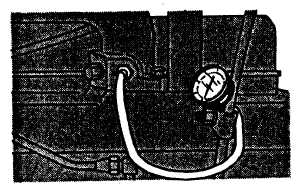
3-7. INTAKE MANIFOLD PRESSURE CHECK.
a.
Remove plug from intake manifold and connect suitable gage to intake manifold, refer to FIGURE 3-1.
FIGURE 3-1. Connecting Test Gage to Intake Manifold
b.
Run engine to bring up to normal operating temperature. (From a cold start, operate engine 10 to 15 minutes at
slow idle.)
NOTE
Engine speed and load should be stabilized before taking readings on gage. Be sure that gage
works properly.
3-19
|
|