ARMY TM 9-2815-255-24
AIR FORCE TO 38G1-95-2
MARINE CORPS TM 2815-24/4
d.
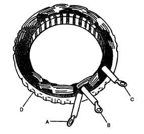
Set multimeter for ohms and check stator (refer to FIGURE 3-11) for open circuits between point D (lamination)
and each terminal A, B, and C. If continuity is noted between lamination and any terminal, stator is defective and
must be replaced.
e.
Set multimeter for ohms and check stator windings (refer to FIGURE 3-11) for continuity between terminals A-B,
A-C, and B-C. If open, replace stator.
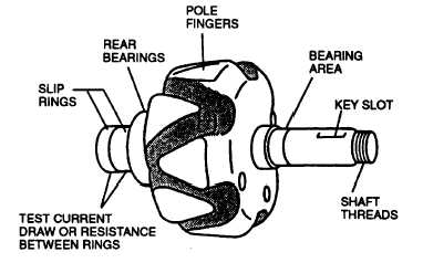
f.
Set multimeter for ohms and check rotor assembly (refer to FIGURE 3-12) for 12.0 to 13.0 ohms indication
between slip rings. Also check that open circuits are indicated between pole fingers and each slip ring. Replace
entire rotor assembly if indications are other than stated.
3-11.6. Assembly.
a.
Using press, install front bearing (32, FIGURE 3-6) in front housing (30).
FIGURE 3-11. Testing Stator Windings
FIGURE 3-12. Testing Rotor
3-32
|
|