ARMY TM 9-2815-256-24
AIR FORCE TO 38G1-96-2
MARINE CORPS TM 2815-24/5
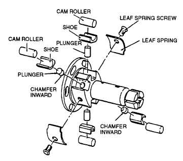
FIGURE 3-90. Installing Rollers and Shoes (Typical)
NOTE
If replacing hydraulic head and rotor, or if replacing leaf springs, do steps n thru s.
n.
Install two leaf springs (26, FIGURE 3-73) on rotor. Secure with two screws (25).
o.
Carefully handle rotor, holding rollers, and shoes in their slots, and install rotor assembly in fixture (19969) on air
inlet side.
Warning
Compressed air can be hazardous when not used properly.
p.
Install fixture (19969) in vise (clamping on flat area) so that air inlet hole is not covered by vise. Install a ¼ 18
NPT fitting in air inlet of fixture. Connect fitting to a supply of clean filtered, compressed air, regulated to a
pressure of 40 to 100 psi (275 to 689 kPa).
NOTE
To set roller-to-roller dimension to specification, turn leaf spring screw (25) inward (clockwise) to
increase, and outward (counterclockwise) to reduce roller-to-roller dimension.
NOTE
The roller-to-roller setting provides a completely accurate maximum fuel adjustment and it should not
differ from value of 95.5 to 96.5 cu.mm/stroke.
q.
Using a micrometer, measure roller-to-roller dimension (distance between outer surfaces of opposed cam rollers).
Dimension should be 1.972 0.0015 inch (50.08 0.038 mm), refer to FIGURE 3-91.
3-109
|
|