ARMY TM 9-2815-256-24
AIR FORCE TO 38G1-96-2
MARINE CORPS TM 2815-24/5P
CAUTION
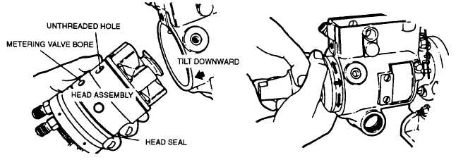
Exercise care not to insert head assembly too far into housing. Pushing head in too far will damage
seal on hydraulic head and result in leakage. Ensure timing mark on drive corresponds with timing
mark on rotor.
aq.
Grasp hydraulic head firmly in both hands and insert it into housing bore with a slight rotary motion. Do not
force. If assembly should jam during insertion, withdraw and start over, refer to FIGURE 3-97.
FIGURE 3-97. Inserting Hydraulic Head (Typical)
ar.
Rotate head assembly until head locking bolt holes line up with their corresponding holes in housing. Insert
two locking bolts (53, FIGURE 3-64) finger tight. as. To prevent governor weights from becoming dislodged
when pump is fully assembled, throttle should be wired in wide open throttle (WOT) position. at. Install vent
wire screw (52).
CAUTION
To prevent damage to special surface treatment, never use an abrasive to clean metering valve (48).
au.
If necessary, assemble arm (45), shim (49), and metering valve (48).
av.
Install spacer (51), shim (50), and metering valve/arm assembly into bore in housing. Depress and rotate
valve several times to ensure freedom of movement. If valve sticks, clean off with clean calibrating oil, refer
to FIGURE 3-98.
3-115
|
|