ARMY TM 9-2815-256-24
AIR FORCE TO 38G1-96-2
MARINE CORPS TM 2815-2415
b.
Install new piston rings (8, FIGURE 3-143) as follows:
(1)
Using piston ring expander, install oil ring expander in bottom ring groove. Position end gap over either
end of piston pin.
(2)
Install oil control ring in bottom ring groove over ring expander. Install with end gap on opposite side of
piston from ring expander gap.
NOTE
A dye stain is added to rectangular and keystone compression rings for added identification.
(3)
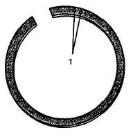
Rectangular compression ring (FIGURE 3-164) is marked with two depressions or with word TOP to
identify top side of ring. Install rectangular compression ring in center ring groove with mark toward top of
piston.
FIGURE 3-164. Compression Ring Identification Marks
(4)
Position gap in rectangular compression ring on opposite side of piston from oil control ring gap.
(5)
Keystone compression ring has a mark to identify top side of ring. Install keystone compression ring in top
ring groove with mark toward top of piston.
(6)
Position gap in keystone compression ring on opposite side of piston from rectangular compression ring
gap.
3-48.2.
Cylinder Block.
a.
If removed, install oil galley and water galley plugs, refer to FIGURE 3-146.
b.
Install piston cooling nozzles, refer to FIGURE 3-155, and tighten to 84 in-lbs (9.5 Nm).
c.
Install cylinder liners, refer to paragraph 3-49.2.
d.
Install crankshaft and main bearings, refer to paragraph 3-43.4.
e.
Install engine front plate and oil bypass valve, refer to paragraphs 3-42.5. and 322.3.
f.
Install camshaft, refer to paragraph 3-40.3.
g.
Install idler gears, refer to paragraph 3-41.3.
h.
Install timing gear cover, refer to paragraph 3-39.3.
i.
Install oil pressure regulating valve, refer to paragraph 3-17.3.
j.
Install crankshaft pulley, refer to paragraph 3-38.3.
3-211
|
|