ARMY TM 9-2815-256-24
AIR FORCE TO 38G1-96-2
MARINE CORPS TM 2815-24/5
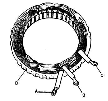
FIGURE 3-11. Testing Stator Windings
POLE
FINGERS
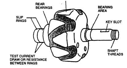
FIGURE 3-12. Testing Rotor
b.
Install front bearing retaining screws (31). Torque screws 25 to 35 in-lbs (2.82 to 3.95 Nm).
c.
Using arbor press, press front housing (30) over rotor assembly (29) until inner bearing race contacts shoulder on
shaft.
d.
Position pulley spacer (27), woodruff key (28), fan (26), and pulley (25) on rotor assembly (29) shaft.
e.
Install lockwasher (24) and nut (23) on rotor assembly (29) shaft. Place rotor assembly in soft jawed vise and
torque nut 35 to 50 ft-lbs (47.5 to 67.8 Nm).
f.
Position stator (22) in front housing (30) with stator leads at top and notches in lamination aligned with bolt holes.
g.
If damaged, replace retainer (21) in rear housing (20).
h.
Position rear housing (20) over slip rings of rotor assembly (29) with front and rear housing bolt holes aligned and
stator leads extending through openings at top of rear housing (20).
3-33
|
|