ARMY TM 9-2815-256-24
AIR FORCE TO 38G1-96-2
MARINE CORPS TM 2815-24/5
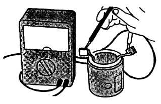
FIGURE 3-38. Checking for Open Field Coil
3-12.6. Assembly.
a.
Install contact (43), end plate (42), washers (41), and screws (40) in magnetic switch assembly (24).
b.
If removed, install nuts (26 and 27, FIGURE 3-15), washers (28 thru 31), lockwashers (32 and 33), and screw
(25).
c.
Apply general purpose grease (630AA) to retainer (20), rollers (21), overrunning clutch (17), steel ball (18), spring
(23), and bearings (34 and 35).
d.
Install washer (22) and spring (23) in magnetic switch assembly (24).
e.
Install five rollers (21), retainer (20), and starter pinion (19) in housing (16).
f.
Place steel ball.(18) in overrunning clutch (17) and install both in housing (16).
g.
Position assembled housing (16) on magnetic switch assembly and secure with three screws (15). Tighten
screws 5.1 to 8.7 ft-lbs (6.9 to 11.8 Nm).
h.
Install armature (14) in magnetic switch assembly (24).
i.
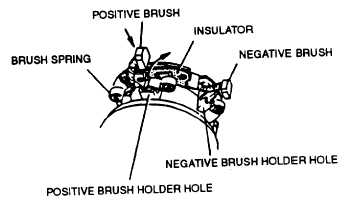
Position brush holder (13). Lift springs and install brushes, refer to FIGURE 3-39. Ensure negative brushes
(connected to brush holder) are installed in negative holes (not insulated) and positive brushes (connected to
yoke) are installed in positive holes (separated from plate with insulator). Ensure positive brush leads are not
grounded.
FIGURE 3-39. Installing Brushes
j.
Position cover (12, FIGURE 3-15) on yoke (39) engaging tab on cover with lead wire grommet, refer
to FIGURE 3-40. Secure with two screws (11, FIGURE 3-15). Tighten screws 1.95 to 3.40 ft-lbs (2.6 to 4.6 Nm).
Change 3
3-49
|
|