ARMY TM 9-2815-257-24
AIR FORCE TO 38G1-128-2
MARINE CORPS TM 10155A/2815-24/3
5-22
5-10. PISTON AND CONNECTING ROD MAINTENANCE - cont.
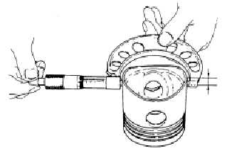
2.
Measure the outside diameter (OD) of piston,
approximately 1/2 inch from the bottom (Figure
5-13). OD must be 3.0591 inches (77.70 mm),
minimum. Replace piston if out of limits.
3.
Measure the internal diameter (ID) of the piston
pin hole in piston. ID must be 0.8295 inch (21.07
mm), maximum. Replace piston if out of limits.
4.
Measure the OD of piston pin (12, Figure 5-15)
along the length of the pin. OD must be 0.8232
inch (20.91 mm), minimum. Replace piston pin if
out of limits.
Figure 5-13. Piston Inspection
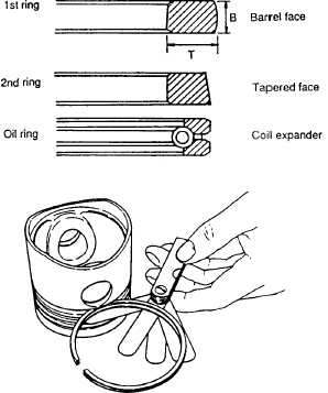
5.
Using new piston ring set, measure the clearance
between piston rings and piston grooves (Figure
5-14). Side clearance must be 0.0059 inch (0.15
mm), maximum. If clearance exceeds limit,
replace piston.
D. INSTALLATION.
1.
Install new ring set into piston ring grooves.
Mount rings with end gaps staggered 120
apart
(see Figure 5-16). Make sure that rings move
smoothly in grooves.
Use extreme caution when handling
hot components. Wear protective
gloves. Failure to observe this
warning can result in injury to
personnel.
2.
To install piston pin (12, Figure 5-15) into piston
(8) and connecting rod (9), heat components to
158 to 176
F (70 to 80
C). Match marks on
piston and connecting rod and install connecting
rod into piston. Install piston pin (12) and allow
components to cool.
Figure 5-14. Piston Ring Groove Clearance
WARNING
|
|