ARMY TM 9-2815-259-24
AIR FORCE TO 38G1-125-2
MARINE CORPS 09249A/09246A-24
5-30
(b)
Rotate the pointer and rotor in the direction of rotation indicated on the pointer
(counterclockwise) until pointer is aligned with specified number of degrees on upper or
outer scale. Mark on hub should line up with zero on locator (where "place timing line
here" arrow point is located). If line is not correct, use abrasive stone to remove incorrect
mark from hub. Place a mark at the correct angle first using a pencil and then with electric
marking pencil.
(c)
Timing mark is now in correct position.
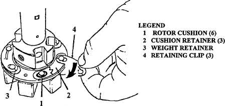
(12) Position rotor cushions (1, Figure 5-36) and cushion retainers (2) on weight retainer (3).
(13) Install retaining clips (4).
FIGURE 5-36. WEIGHT RETAINING ASSEMBLY.
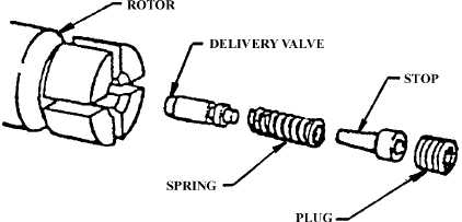
(14) Install delivery valve (98, Figure 5-1) using delivery valve extractor (26081).
(15) Install spring (97), delivery valve stop (96), and screw (95) in rotor (86). Position rotor in fixture
(16313) and secure fixture in vise. Torque screw (95) to 120 to 125 lb-ft (13.6 to 14.1 Nm). Refer
to Figure 5-37.
FIGURE 5-37. TIGHTENING DELIVERY VALVE STOP SCREW
|
|