ARMY TM 9-2815-260-24
AIR FORCE TO 38G1-126-2
MARINE CORPS TM 09244A/09245A-24
4-89
(3)
Install flywheel housing, refer to step 4.8.3.d.
d. Installation.
(1)
Remove all covering installed during step 4.8.3.a.(5).
(2)
Insure all gasket material is removed from sealing surfaces.
(3)
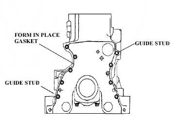
Apply Flexible Form-In-Place Gasket (Appendix E) in a continuous 0.06 - 0.08 in. (1.5 - 2 mm)
thick bead (A) to cylinder block as shown in Figure 4-58. Ensure that sealant bead is located in
center of mating surfaces and completely encircle bolt holes.
(4)
Install two guide studs in bolt holes (Figure 4-60).
__________
WARNING
Flywheel housing is heavy. Provide adequate lifting device to support
weight. Failure to comply could result in serious personal injury.
(5)
Using guide studs, position flywheel housing on cylinder block and install bolts finger tight.
FIGURE 4-59. GASKET APPLICATION TO CYLINDER BLOCK
(6)
Remove guide studs and install remaining bolts finger tight. Torque all attaching bolts, using a
cross pattern, to 92 lb-ft (125 Nm).
(7)
Check flywheel housing seal bore run out as follows:
(a)
Attach magnetic base of dial indicator to flywheel end of crankshaft.
(b)
Position dial indicator against inner diameter of seal bore in flywheel housing and zero
dial indicator.
(c)
Turn crankshaft 360 degrees from front of engine while observing dial indicator.
Maximum permissible run out of flywheel housing seal bore is 0.006 in. (0.0152 mm).
Replace flywheel housing if run out exceeds specification.
|
|