ARMY TM 9-2815-260-24
AIR FORCE TO 38G1-126-2
MARINE CORPS TM 09244A/09245A-24
5-36
(41)
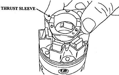
Install thrust sleeve (Figure 5-46).
FIGURE 5-46. THRUST SLEEVE INSTALLATION (TYPICAL).
(42)
Install fuel injection pump housing on mounting plate (Refer to Appendix F, Figure F1) and
secure in vice with hydraulic head bore tilted downward approximately 30-45 degrees.
(43)
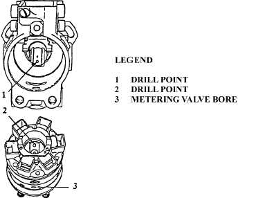
Rotate drive shaft until drill point (1, Figure 5-47) on end is in 6 o’clock position. Apply light
coating of lubricant (22204) to hydraulic head seal (87, Figure 5-1) and to entrance to fuel
injection pump housing.
FIGURE 5-47. HEAD AND ROTOR ASSEMBLY INSTALLATION (TYPICAL).
|
|