ARMY TM 9-2815-260-24
AIR FORCE TO 38G1-126-2
MARINE CORPS TM 09244A/09245A-24
5-44
(68)
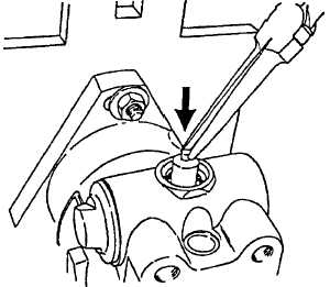
Align pin hole in piston with hole in cam ring and install cam pin. Refer to Figure 5-60.
FIGURE 5-60. ALIGNING PIN HOLE IN PISTON
(69)
Install two new O-ring seals (29, Figure 5-1) to the spring side piston hole plug. Assemble the
trimmer screw (33), a new O-ring seal (34) and the locknut (32)(chamfered side facing seal) to
spring side plug (28).
(70)
Assemble the advance spring guide (31) and the advance spring(s) (30) to the trimmer screw (33).
(71)
Install spring side plug assembly (28) to housing (1) and tighten to 455 to 505 lb-in (51.5 to 57.2
Nm).
(72)
Use wrench to tighten the power side plug to 455 to 505 lb-in (51.5 to 57.2 Nm).
(73)
Install new seal (25) to cam pin hole plug (24) and install plug (24). Tighten to 75 to 100 lb-in
(8.5 to 11.3 Nm).
(74)
Tighten head locating screw (24) to 180 to 220 lb-in (20.0 to 25.0 Nm).
(75)
Invert pump and holding fixture in vise and tighten the two head locking screws (23) to 180 to 220
lb-in (20.0 to 25.0 Nm).
(76)
Using end cap wrench, tighten the transfer pump end cap (72) to 360 to 440 lb-in (41.0 to 50.0
Nm).
(77)
Assemble the transfer pump end cap locking plate (21) and the new seal (22) to screw (20) and
install locking plate assembly to hydraulic head (48). Tighten screw to 70 to 80 lb-in (7.9 to 9.0
Nm).
(78)
If pump is not equipped with a torque screw, install torque screw hole plug and new seal and
tighten to 75 to 100 lb-in (8.5 to 11.3 Nm).
|
|