ARMY TM 9-2815-260-24
AIR FORCE TO 38G1-126-2
MARINE CORPS TM 09244A/09245A-24
5-55
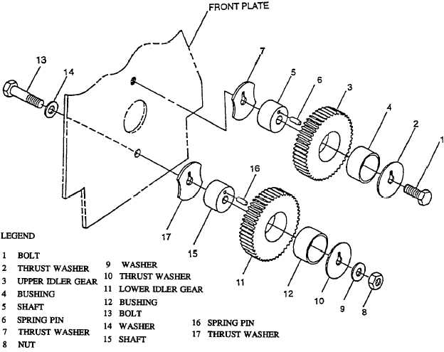
FIGURE 5-63. IDLER GEARS
c. Test.
(1)
Measure upper and lower sleeve bushing (4 and 12, Figure 5-63) inner diameter. Refer to Table 5-
4 for specifications.
(2)
Measure upper and lower shaft (5 and 15) outer diameter. Refer to Table 5-4 for specifications.
(3)
Oil clearance is required between upper and lower bushing to shaft. Refer to Table 5-4 for
specifications. If oil clearance exceeds limit, replace worn parts.
(4)
If necessary, replace worn idler gears (3 and 11 Figure 5-63), shaft (5 and 15) or bushing (4 and
12).
(5)
If sleeve bushings (4 and 12) were removed, use an arbor press, driver and handle to install sleeve
bushing (4) in idler gear (3) and sleeve bushing (12) in idler gear (11).
|
|