ARMY TM 9-2815-260-24
AIR FORCE TO 38G1-126-2
MARINE CORPS TM 09244A/09245A-24
5-80
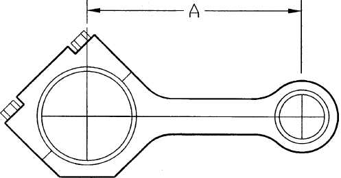
FIGURE 5-77. MEASURING ROD CENTER-TO-CENTER BORES
(3) Assemble the pistons and connecting rods per the following steps:
NOTE
If new piston and liner assembly is to be installed, leave piston inside liner.
Push piston out of liner bottom only far enough to install piston pin.
(a)
Lubricate piston pin (9, Figure 5-72),connecting rod piston pin bushing (10), and piston
pin bore in piston (4) with clean engine oil.
CAUTION
Install pistons on same connecting rods as pistons were removed from. Use
new piston pin snap rings. Failure to comply could result in excessive
engine wear or engine failure.
(b)
Assemble piston (4) and matching connecting rod. Ensure that the word "FRONT" on
side of piston and side of connecting rod are facing same direction..
(c)
Insert piston pin into piston pin bore in piston and through connecting rod piston pin
bushing.
(d)
Install new snap rings (8) with sharp edge of ring facing away from piston pin. Ensure
that snap rings are seated in grooves of piston pin bore.
CAUTION
Do not over expand piston rings. Piston rings can be damaged if expanded
too far. Expand piston rings only as far as necessary to install rings on
piston. Failure to comply could result in engine failure.
|
|