ARMY TM 9-2815-260-24
AIR FORCE TO 38G1-126-2
MARINE CORPS TM 09244A/09245A-24
5-106
(c)
Clean and inspect valves, valve stems, valve stem tips, and retainer lock groove for
cracks, wear, or evidence of physical damage. Replace valves that are worn or damaged.
(d)
Measure valve stem outer diameter with outer diameter micrometer. Record
measurements and compare with valve guide inner diameter, refer to step 4 (i). Replace
valves not within specifications.
NOTE
Intake valve has a larger head outer diameter and is also identified with a
dimple on valve head.
1
Intake valve outer diameter should be 0.3096 - 0.3104 in. (7.864 - 7.884 mm).
2
Exhaust valve outer diameter should be 0.3090 - 0.3100 in. (7.848 - 7.874 mm).
(e)
Use valve inspection center (D-05058ST) to determine if valves are out of round, bent or
warped. Maximum valve face runout is 0.0015 in. (0.038 mm). Replace valves not
within specifications.
CAUTION
Do not nick valve head-to-stem radius while grinding valves. A nick could
cause valve to break. Break all sharp edges after grinding valve. Failure to
comply could result in damage to engine.
(f)
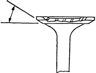
Reface valve to 29.25° ± 0.25° using valve refacing station, refer to Figure 5-90.
(4)
Clean, inspect, and measure cylinder head as follows:
(a)
Inspect combustion face for evidence of physical damage, oil or coolant leakage, or
gasket failure. Repair or replace cylinder head if there is evidence of physical damage;
such as cracking, abrasion, distortion, or valve seat “torching”. Inspect all cylinder head
passages for restrictions.
FIGURE 5-90. VALVE FACE ANGLE
|
|