TM 9-2920-243-34
c. Shift Housing Assembly.
(1) Inspect shift housing for cracks or
distortion and burs on mating flange and packing
surfaces. Replace if damaged.
(2) Inspect bushing-type bearing for score
marks and wear patterns. Check bearing against
limits specified in repair rebuild standards (para
3-31e) and replace (para 3-15c) if worn beyond
limits.
(3) If the bushing.type bearing is removed
from the shift housing, check diameter of bearing
bore against limits specified in repair and rebuild
standards (para 3-31e). Replace shift housing if
worn beyond limits.
d. Drive Assembly.
(1) Inspect bearing surface and drive
assembly internal splines for score marks and
wear patterns. Replace drive if worn or damaged.
(2) Check drive spring against limits
specified in repair and rebuild standards (para 3-
31a) and replace spring if it is not within these
limits.
(3) Inspect drive collar for signs of wear and
distortion and replace drive assembly if either
condition exists.
(4) Inspect gear teeth for wear pattern and
replace drive assembly if wear is excessive.
e. Brush Holder Assemblies and Brushes.
(1) Inspect brush holder and spring
assemblies for any visible damage. Replace if
damaged. Check brush spring tension with a 0 to
40 ounce spring scale. It should require ap-
proximately 36 ounces to lift end of spring out of
brush holder. If tension is less than 30 ounces,
replace holder and spring assembly.
(2) Inspect brushes for chips, cracks, loose
terminal leads, and grease spots. Check length of
brushes against limits specified in repair and
rebuild standards (para 3-31a.). Replace brushes
if worn beyond these limits.
f. Field Ring Assembly.
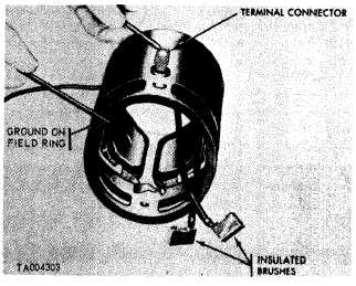
(1) Check field coils for insulation breakdown
with an ohmmeter. Attach one probe of ohmmeter
to field coil terminal and the other probe to field
ring (fig. 3-25). The minimum reading should not
be less than one megohm. If field coils are
damaged, replace starter.
(2) Inspect field frame for cracks and burs.
Replace starter if cracked.
Figure 3-25. Testing field coils for grounds.
g. Armature Assembly.
(1) Inspect commutator contact surface of
armature. A satisfactory condition is indicated by
an even, highly burnished, dark-copper color. If
contact surface is rough, pitted, scored, burned,
or coated with hard carbon or oil, commutator
must be cleaned or resurfaced as necessary,
provided it is in good electrical and mechanical
condition as a result of following inspection.
Check armature against limits specified in repair
and rebuild standards (para 3-31 a) and replace
starter if it is not within these limits. Inspect
splines of armature shaft for wear or damage and
replace starter if either condition exists.
(2) Inspect armature for grounds with a test
light by touching one probe to commutator bar
riser and other to armature core (fig. 3-26). Test
all commutator bars in this manner. If test light
glows, armature is grounded and starter must be
replaced.
(3) Inspect armature for short circuits with a
growler. Place armature in growler and hold a
thin strip of steel, such as a hacksaw blade, about
1/32 to 1/16-inch away from armature core as
shown in figure 3-27. While holding steel strip in
position, rotate armature slowly in growler. A
short circuit will pull the steep strip tightly
against armature core and cause strip to vibrate.
If a short circuit is found, starter must be
replaced.
3-10
|
|