TM 9-2920-243-34
3-18. Brush Rigging Assembly
a. Refer to paragraph 3-12 and reverse
disassembly for assembly of brush rigging
assembly. Do not install jumper (A, fig. 3-21) as
shown.
NOTE
The brush holders (D, fig, 3-22) are
designed to overlap each other at brush
holders supports when in assembled
position and must be installed properly.
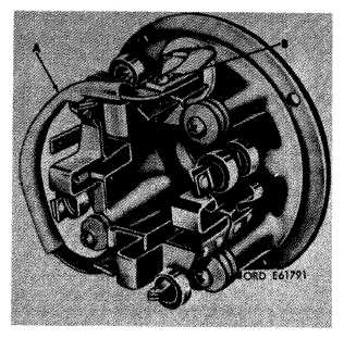
b. Position jumper coil (A), as shown in figure
3-35, on brush rigging assembly and hold it in
position using one screw (B).
Figure 3-35. Position jumper on brush rigging assembly.
3-19. Installation of Brush Rigging Assembly
Refer to paragraph 3-11 and reverse removal
instructions for installation of brush rigging
assembly. Make certain scribe marks (A, fig. 3-
20) are alined.
3-20. Installation of Armature Assembly and
Brushes
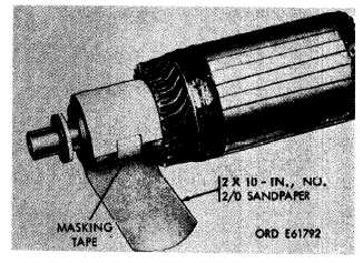
a. Position sandpaper on armature as shown in
figure 3-36 and secure one end with masking tape.
Install armature as instructed in paragraph 3-10.
Figure 3-36. Positioning sandpaper on armature.
b. Refer to paragraph 3-11c and reverse
removal instructions for installation of brushes in
brush holders. Make certain brush springs hold
brushes securely against armature.
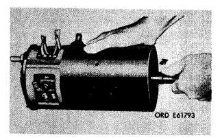
c. Rotate armature clockwise as shown in figure
3-37 to seat brushes. Continue this procedure
until a proper brush seat has been obtained as
shown in figure 3-38.
Figure 3-37. Rotating armature to seat brushes.
3-16
|
|