
| Tweet |

Custom Search
|
|

|
||
 ARMY TM 9-6115-666-13&P
AIR FORCE TO 35C2-3-505-1
5.8. ELECTRICAL LEADS MAINTENANCE (Continued).
INSTALLATION
1. Position new lead in place.
2. Connect lead as indicated on wiring diagram FO-1 and table 5-1.
3. Install panel covers and switch box cover.
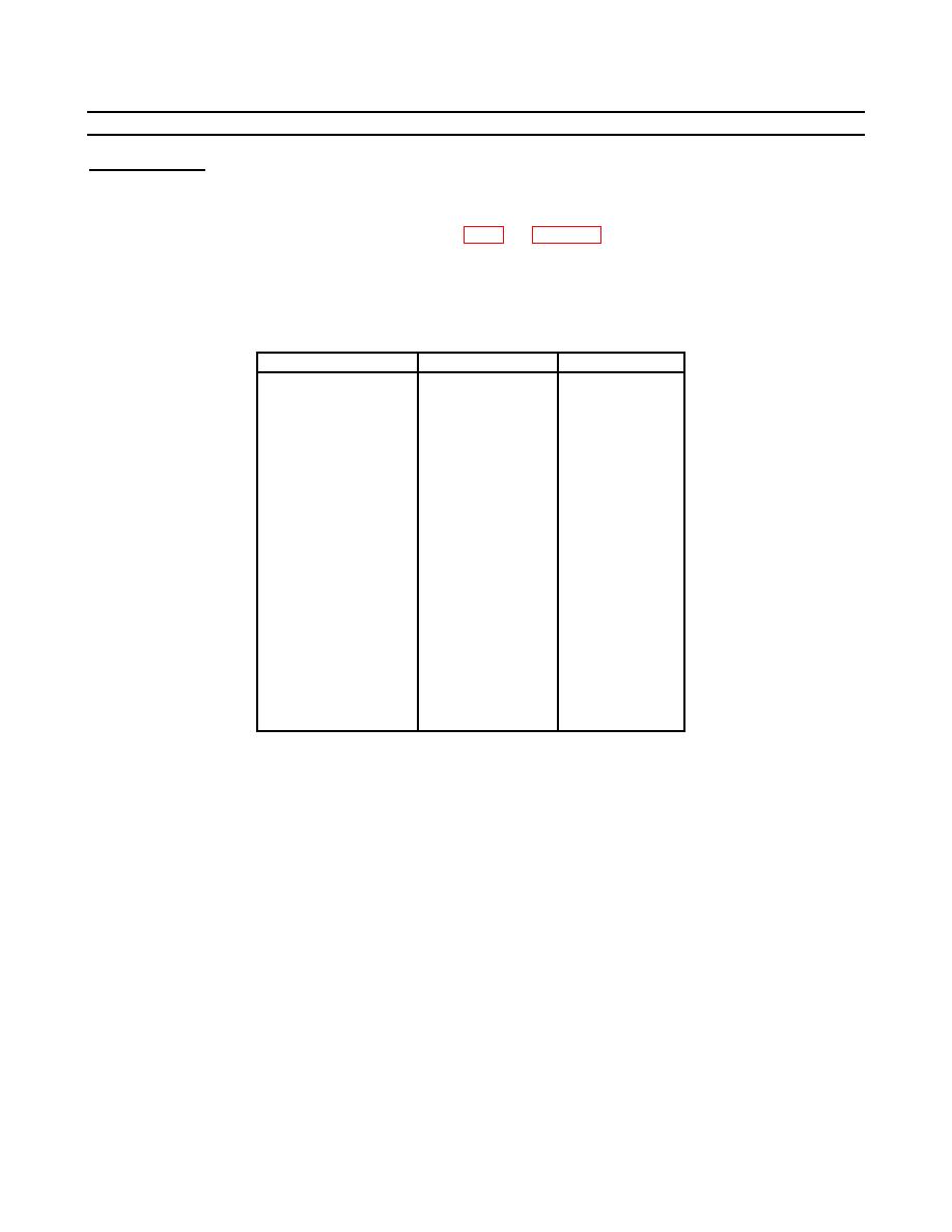
Table 5-1. Electrical Leads.
Wire Identification
From
To
A1W10
A1S1-1
A1W1-5(L1)
A1W11
A1S1-3
A1W2-5(L2)
A1W12
A1S1-5
A1W3-5(L3)
A1W13
A1S2-1
A1W1-5(L1)
A1W14
A1S2-3
A1W2-5(L2)
A1W15
A1S2-5
A1W3-5(L3)
A1W16
A1W5-1(GND)
A1W4-1(N)
A1W17
A1W5-2(GND)
A1E1-(GND)
A1W18
A1CB1-LN5
A1W1-1(L1)
A1W19
A1CB1-LN3
A1W2-1(L2)
A1W20
A1CB1-LN1
A1W3-1(L3)
A1W21
A1CB2-LN5
A1W1-2(L1)
A1W22
A1CB2-LN3
A1W2-2(L2)
A1W23
A1CB2-LN1
A1W3-2(L3)
A1W24
A1CB3-LN5
A1W1-3(L1)
A1W25
A1CB3-LN3
A1W2-3(L2)
A1W26
A1CB3-LN1
A1W3-3(L3)
A1W27
A1CB4-LN5
A1W1-4(L1)
A1W28
A1CB4-LN3
A1W2-4(L2)
A1W29
A1CB4-LN1
A1W3-4(L3)
5-13
|
||
|
||


