
| Tweet |

Custom Search
|
|

|
||
 TM 9-8000
e. Usage. Rotary engines are in use in passenger
automobiles and small equipment such as snowmobiles.
The engines usually are made in a two-rotor
configuration as shown in figure 2-30. A two-rotor design
is equivalent to a four-cylinder, four-stroke cycle piston
engine.
Figure 2-30. Two-Rotor Configuration
Section III. CLASSIFICATION OF PISTON ENGINES
automotive applications. The liquid-cooled engine is
2-17. Classification by Methods of Cooling.
identified by the remote radiator and associated
plumbing. A typical liquid-cooled engine is shown in
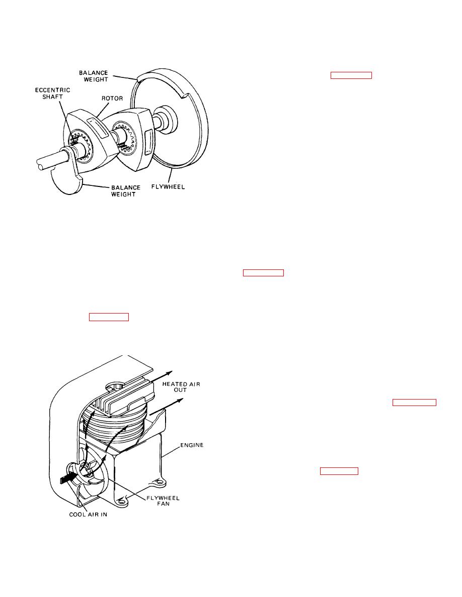
a. Air Cooled. Engines that use air as a cooling
medium generally are used in aircraft and small
equipment such as motorcycles, snowmobiles, and
2-18. Classification by Valve Arrangement.
An
gasoline power equipment.
The air-cooled engine
engine can be classified by the arrangement of its valves
usually is identified by removable cylinders with cooling
and valve train configuration. The various valve train
fins covering the outside surfaces. A typical air-cooled
configurations may be grouped into two categories based
engine is shown in figure 2-31.
on the location of the valves. The first category is the
group of engines with the valves located beside the
b. Liquid Cooled. Engines that use liquid as a cooling
pistons and cylinders, in the cylinder block. The second
medium are used in the majority of
category is the group of engines with the valves located
over the pistons in the cylinder heads.
a. Valves in the Cylinder Block. These engines are
known as flathead engines. This is due to the fact that
the cylinder head is shaped like a flat slab. A typical
flathead engine cylinder head is shown in figure 2-33.
The cylinder head's only functions are to complete the
combustion chamber and to hold and locate the spark
plug. Flathead engines are virtually obsolete in all
current automotive applications. The configuration of
valve trains that were used in flathead engines are as
follows.
(1) T-Head (Fig. 2-34). The intake and the
exhaust valves were located on opposite sides of the
cylinder, each requiring their own cam-shaft. The T-head
engine got its name from the imaginary letter formed by
the piston and the valve heads
Figure 2-31. Typical Air-Cooled Arrangement
TA233330
2-22
|
||
|
||


