
| Tweet |

Custom Search
|
|

|
||
 TM 9-8000
+Figure 3-51. Valve Rotators.
roller link chain may have a single or a double row of
slipping on the sprockets, provide more precise
links.
valve timing, and compensate for component stretch
and wear. Engines with belt-drive configuratlons
(3) Belt Drive (C, Fig. 3-53). Sprockets on the crankshaft
usually use a spring-loaded idler wheel. Chain-
and the camshaft are linked by a continuous neoprene
driven configurations usually use a fiber rubbing
belt. The belt has square-shaped Internal teeth that
block that Is either spring loaded or hydraulic. The
mesh with teeth on the sprockets. The timing belt is
hydraulic tensioner Is a device that works by the
reinforced with nylon or fiberglass to give It strength and
same principle as a hydraulic lifter (para 3-13h(2)).
prevent stretching. This drive configuration Is limited to
The hydraulic tensioner Is much more desirable for
overhead camshaft engines.
use with a rubbing block because it takes up the
slack in the chain without exerting excessive
e. Timing Belt and Chain Tensioners (Fig. 3-53). Most
pressure, resulting in longer component life.
engines with chain-driven and all engines with belt-
f.
Timing Marks (Fig. 3-53) The camshaft and the
driven camshafts employ a tensioner. The tensioner
crankshaft always must remain In the same relative
pushes against the belt or chain to keep It tight. This
position to each other. Because the
serves
to
keep
It
from
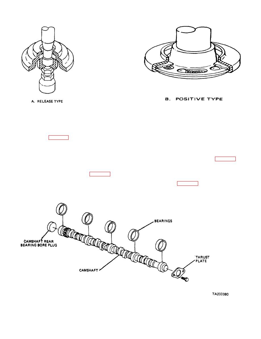
Figure 3-52. Camshaft Support.
3-30
|
||
|
||


