
| Tweet |

Custom Search
|
|

|
||
 TM 9-8000
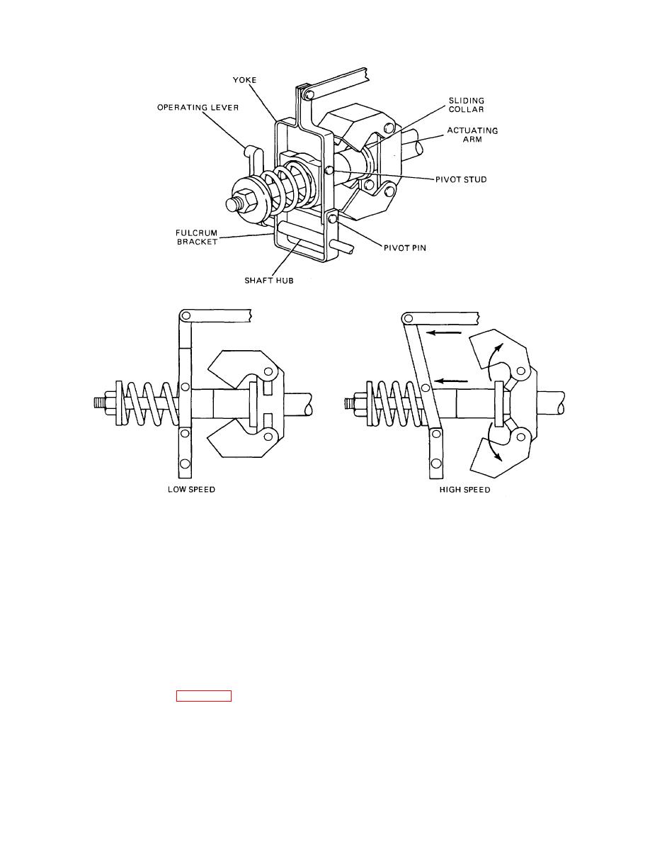
Figure 5-23. Mechanical (Centrifugal) Governor.
spring and the flyweights, effectively changing the engine
through a venturi located in the air-intake manifold. The
speed for any given load.
governor consists essentially of an atmospheric
suspended diaphragm connected by linkage to the
d. To accelerate the vehicle with a given load, the
control rod of the injection pump. The chamber on one
side of the diaphragm is open to atmosphere, and on the
foot throttle Is depressed, which in turn increases the
other side it is sealed and connected to the venturi in the
governor spring tension.
The increase in tension
manifold. In addition, there is a spring acting on the
causes the governor sleeve to move the control rod
sealed side of the chamber, which moves the diaphragm
through the yoke toward the full-fuel position. As engine
and the control rod to the full-fuel position normally.
speed increases, the flyweights will move outward until
they reach the point of equilibrium with the governor
b. When the engine is running, the pressure In the
spring. At this point, engine speed will stabilize.
sealed chamber is reduced below the atmospheric
pressure existing in the other chamber.
5-27.
Vacuum Governors (Fig. 5-24).
TA233459
a. The vacuum governor operates by utilizing the
pressure drop created by the velocity of the air passing
5-31
|
||
|
||


