
| Tweet |

Custom Search
|
|

|
||
 TM 9-8000
Section IV. FUEL SYSTEM
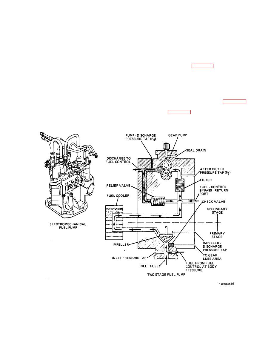
design an impeller is used for the first-stage pressure
10-14. Requirements. The fuel system is designed to
increase. The fuel then is routed to a heat exchanger to
provide the engine with the proper amount of fuel under
cool the pressurized fuel. A gear pump then is used for
all operating conditions. The fuel systems incorporated
the final pressure increase. A pressure relief valve also
on gas turbine engines range from simple valves to
is used to limit the amount of pressure the pump
complex microprocessor control assemblies. The fuel
develops at high speed (fig. 10-18).
control system can receive inputs from one or two
sources on some models, while other systems monitor
10-16. Fuel Nozzles. Fuel nozzles are used to induce
multiple engine variables. Basically, these fuel systems
are categorized into either a hydro-mechanical or
fuel into the combustion chamber. They are designed to
electronic group.
produce an accurately shaped spray pattern and
maintain combustion during varying engine operating
conditions. injection nozzles generally are either the
10-15. Fuel Pumps. Fuel pumps are used to pressurize
single or dual spray pattern design (fig. 10-19). The
the fuel prior to injection into the combustion chamber.
single nozzle provides one spray pattern of fuel under all
Gear pumps (para 20-4) generally are used to generate
conditions (fig. 10-19). The dual nozzle is designed to
the fluid pressure required for operation. Some pumps
provide
a
single
spray
pattern
at
low
are designed as a two-stage configuration.in this
Figure 10-18. Gas Turbine Fuel Pumps
10-15
|
||
|
||


