
| Tweet |

Custom Search
|
|

|
||
 TM 9-8000
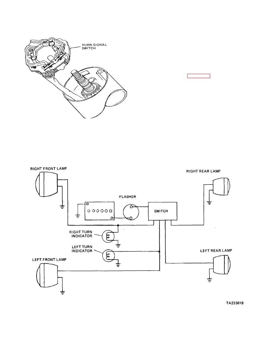
switch. When the turn signal switch is turned off, it must
pass stoplight current to the rear lamps. As a left or right
turn signal is selected, the stoplight circuit is opened and
the turn signal circuit is closed to the respective rear
lamp. Also note that when this circuit is used, the front
and instrument lamps must be on a separate switch
circuit.
unit creates the flashing of the turn signal lamps. It
consists basically of a bimetallic strip (two dissimilar
metals bonded together) wrapped in a wire coil. The
bimetallic strip serves as one of the contact points.
(1) When the turn signals are actuated, current
flows into the flasher, first through the heating coil to the
bimetallic strip, then through the contact points and out
Figure 16-18. Typical Turn Signal Switch
of the flasher, where the circuit will be completed through
the turn signal lamps.
(2) A common design for a turn signal system is
to use the same rear lamps for both the stop and turn
(2) The current flowing through the heating coil
signals. This complicates the design of the switch
will heat the bimetallic strip, causing its dissimilar metals
somewhat. Note that the stoplight circuit must pass
to expand at different rates. This
through
the
turn
signal
Figure 16-19. Typical Turn Signal Wiring Diagram
16-13
|
||
|
||


