
| Tweet |

Custom Search
|
|

|
||
 TM 9-8000
gage whose operation is the same as the gage used with
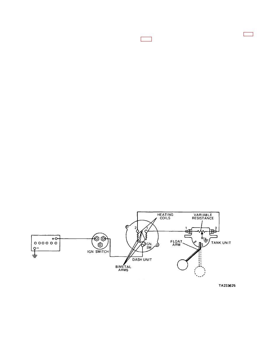
c. Thermostatic Fuel Gage: Differential Type (Fig.
the self-regulating system described ir paragraph 17-3a.
The differences in the system are the use of a variable
instrument panel gage whose operating principles are
resistance fuel tank sending unit and an external voltage-
much the same as the thermostatic gage described In
limiting device. The sending unit controls the gage
paragraph 17-3a. The differential-type thermostatic gage,
through the use of a rheostat. A rheostat is a wire wound
however, uses two electrically heated bimetallic strips
resistance unit whose value varies with it' effective
that share equally in operating and support- ing the gage
length. The effective length of the rheostat is controlled
pointer. The pointer position is obtained by dividing the
in the sending unit by sliding brush that is operated by
available voltage between the two strips (differential).
the float arm. The power supply to the gage is kept
The tank unit is a rheostat type whose operating
constant through the use of a voltage limiter. The voltage
principles are much the same as the tank unit described
limiter consists of a set of contact points that arc
in paragraph 17-3b. The tank unit in this system,
controlled by an electrically heated bimetallic arm.
however, contains a wire-wound resistor that is
connected between two external terminals. Each one of
(1) When the fuel tank is empty, the float lays on
the external terminals connects to one of the instrument
the bottom. The float arm will position the contact brush
panel gage bimetallic strips. The float arm moves a
so that the full length of the rheostat resistor will be
grounded brush that raises resistance progressively to
utilized. The resulting high resistance will drop voltage to
one terminal, while lowering the resistance to the other.
the gage sufficiently so that the pointer will rise only to
This causes the voltage division and resulting heat
empty.
differential to the gage strips that formulate the gage
readings. Two additional bimetallic strips are provid- ed
(2) As the fuel level rises in the tank, the float
for temperature compensation. In addition, one of these
will raise the float arm, which, in turn, will move the
blades operates contact points to limit voltage to
contact brush on the rheostat resistor. As the float arm
approximately 5 volts.
moves upward, the resistance will decrease
proportionally, resulting in a proportional voltage increase
(1) When the tank is half full, the float arm
to the gage. The gage readings will increase
positions the contact brush midway of the rheostat. This
proportionally, resulting in accurate readings of the fuel
causes equal resistance values to each sending unit
level in the tank.
circuit, resulting in equal heating of the gage bimetallic
strips, causing the gage to read one-half.
(3) The voltage limiter effectively will en- sure a
constant supply of current regulated to the equivalent of
(2) Fuel levels above or below half will cause
5 volts, to provide accurate gage readings regardless of
the tank unit to divide the voltage to the gage bimetallic
electrical
system
voltage
variations.
strips
in
the
correct
to
Figure 17-8. Thermostatic Fuel Gage: Differential Type
17-6
|
||
|
||


