
| Tweet |

Custom Search
|
|

|
||
 TM 9-8000
ted suitable high-temperature and humidity resistance in
practical for the identification of circuits in future military
these applications.
Tape 19207-10886484 has
vehicle electrical systems. There are several practical
demonstrated adhesive qualities that withstand steam
methods used to apply wire identification characters on
cleaning and the oily, high-temperature environment
wiring assemblies. Four of the commonly employed
associated with vehicle power packs.
methods are:
a. Lettering may be hot stamped per MIL-M-81531,
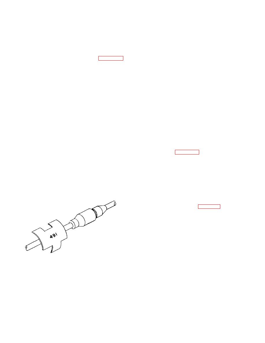
17-23. Wiring Harness Identification (Fig. 17-35).
with 0.05-in. minimum height type, directly on the wire or
Wires in an electrical system should be identified by a
cable insulation using white letters on dark backgrounds
number, color, or code to facilitate tracing circuits during
or black letters on light backgrounds.
assembly, troubleshooting, or rewiring operations. This
identification should appear on wiring schematics and
b. Lettering may be hot stamped per MIL-M-81531,
diagrams and whenever practical on the individual wire.
with 0.05-in. minimum height type, on MIL-1-23053/2
The assigned identification for a continuous electrical
heat-shrinkable sleeving, length and diameter as
connection should be retained on a schematic diagram
required, assembled over the wire insulation.
until the circuit characteristic is altered by a switching
point or active component. An extension of this system
c. Lettering may be indented or embossed with
involves the use of suffix letters on wiring diagrams and
0.093-in. minimum height type on band, marker blank,
wiring assemblies to identify the segments of wires
MS39020, style and length as required, in accordance
between terminals and connector contacts. The use of
with MIL-STD-130. Of these, the metal marker bands
suffix letters is advantageous when it is necessary to
with indented or embossed characters are the most
identify several individual wires of a common circuit that
durable and they remain legible even if painted over.
are bound in the same harness.
Tank-automotive electrical circuits have been identified
17-24. Wire Terminal Ends.
over the years with unique numbers for specific circuits,
based on the premise that maintenance personnel would
a. General (Fig. 17-36). Wire lug terminals are
become familiar with wire numbers for these circuits and
divided into two major classes: the solder type; and the
this familiarity would facilitate their ability to service a
solderless type, which also are called the pressure or
variety of vehicles. Furthermore, common standard
crimp type. The solder type has a cup in which the wire
automotive electrical components in the supply system
is held by solder permanently, whereas the solderless
such as headlight, taillight, and stoplight switch
type is connected to the wire by special tools that deform
assemblies are marked with these standard wire
the barrel of the terminal and exert pressure on the wire
numbers. Therefore, these numbers should be used to
to form a strong mechanical bond and electrical
the maximum extent
connection. Solderless-type terminals gradually have
replaced solder-type terminals in military equipment.
b. Solderless Terminals (Fig. 17-36).
Solderless terminals come in a variety of designs. Some
of the more common recommended terminals are the
ring-tongue, rectangular-tongue, and flag types. One of
the major sources of trouble when a terminal is
connected to a wire has always been the breakage of the
wire near its junction with the terminal. Wire failures
have been decreased by adding a sleeve to the basic
terminal. The inside diameter of the sleeve is slightly
larger than the outside diameter of the wire
insulation. In the crimping operation, when the
Figure 17-35. Wire Identification.
TA233645
17-28
|
||
|
||


