
| Tweet |

Custom Search
|
|

|
||
 TM 9-8000
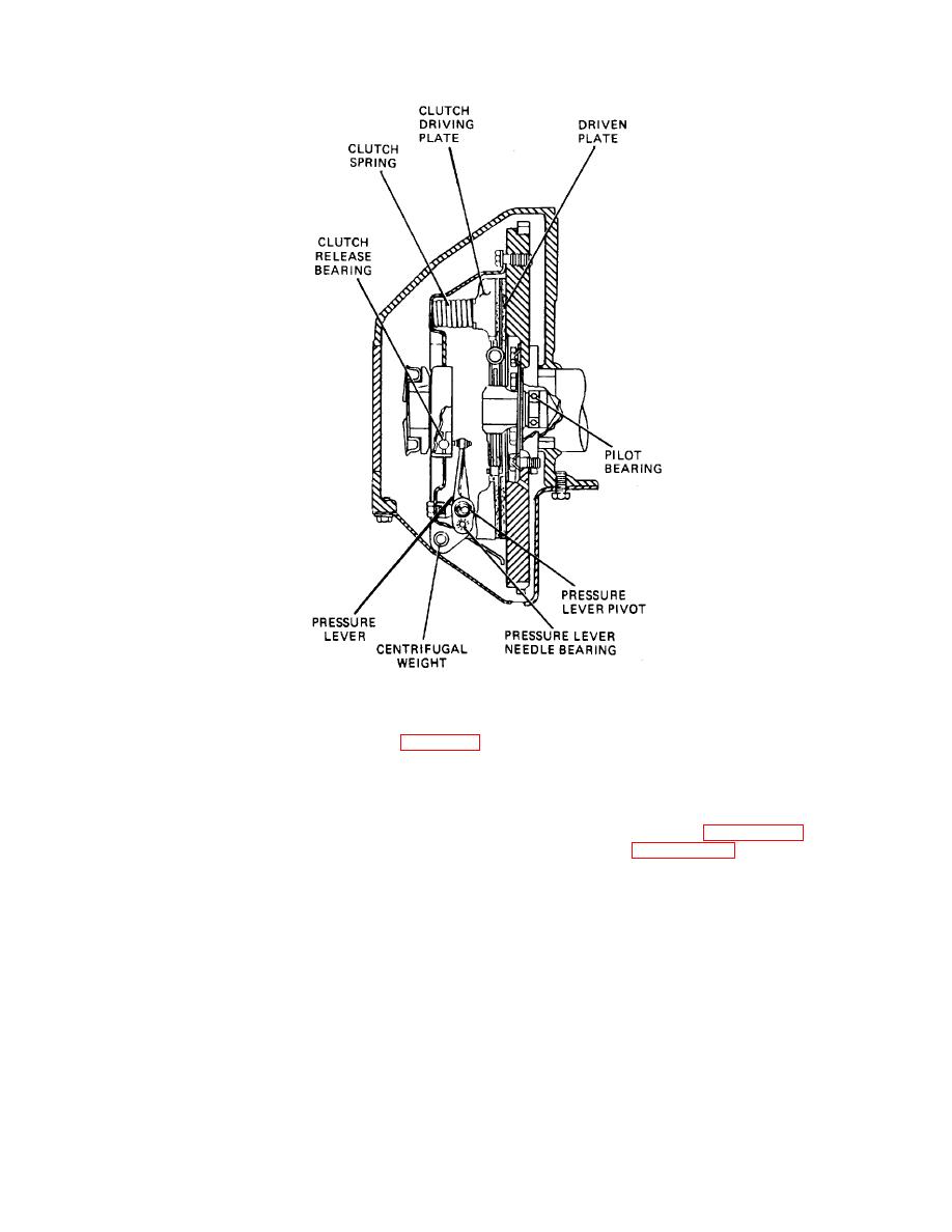
Figure 21-13. Semicentrifugal Clutch - Cross Sectional View.
used either with a conventional clutch and transmission
or as a part of an automatic transmission, in which case,
a. Coupled Phase. The fluid coupling consists of an
it may replace the clutch. The principle of this type of
impeller, or driving torus, driven by the engine and a
drive is illustrated by the action of two electric fans facing
turbine, or driven torus, mounted on the driven shaft.
each other, one with the power connected and the other
These parts are shown In figure 21-14 and depicted
with the power disconnected. As the speed of the power-
schematically in figure 21-15. There is no metallic
driven fan is increased, the flow of air transmits power to
connection between the two torus members. The
the motionless fan and it begins to rotate. The free-
assembly is kept filled with oil under control of a relief
running fan gains speed until It Is rotating almost as
valve, by means of high-capacity pumps. When the
rapidly as the power-driven fan. The same action takes
crank-shaft and impeller rotate, the oil Is thrown by
place In the fluid coupling except that oil, instead of air,
centrifugal force from the center to the outside edge of
transmits the power.
the impeller between the vanes. This increases the
velocity of the oil and increases its
TA233684
21-12
|
||
|
||


