
| Tweet |

Custom Search
|
|

|
||
 TM 9-8000
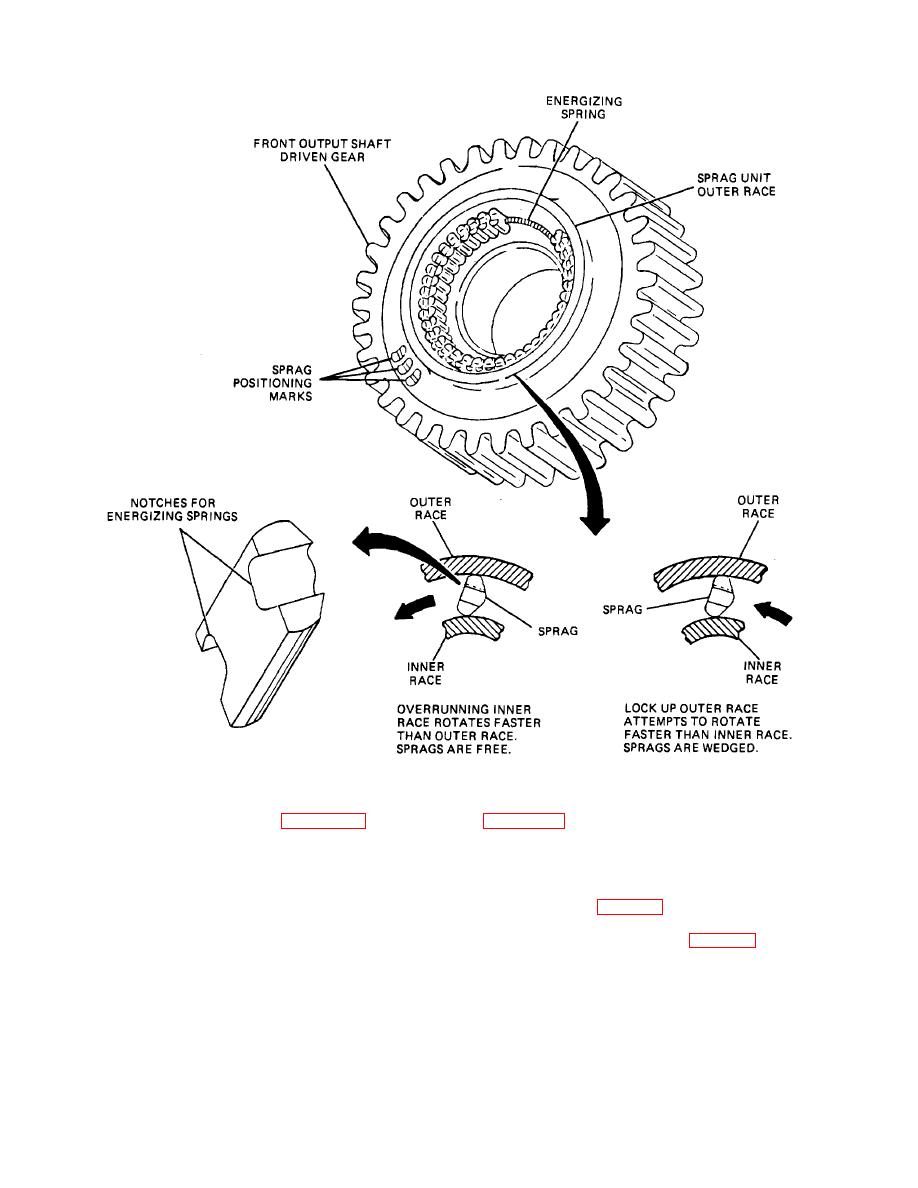
Figure 27-6. Transfer Assembly Sprag Unit.
b. Air-Operated Shift Control Figure 27-7 shows the
power flow in the transfer unit using the air-controlled
and transfer assembly using an air-controlled double-
double-sprag unit. The double-sprag unit has the same
sprag unit. When the transmission is in neutral or a
function as that described in paragraph 27-9, the basic
forward gearshift position, and there is compressed air in
difference being that there is an air valve on the
the compressed air system of the vehicle, the air cylinder
transmission low-and reverse-shifter shaft, which
control valve (1, fig. 27-8) will be positioned to admit air
automatically shifts the sprag unit to forward or reverse
under pressure from the compressed air system into the
whenever the main transmission is shifted to forward or
shift air cylinder assembly (8, fig. 27-8). The air then is
reverse.
admitted to the forward-shift side of the spring-balanced
piston in the cylinder. The piston then is moved,
c. Air-Operated Shifter Operation. Shown in
TA233766
27-7
|
||
|
||


