
| Tweet |

Custom Search
|
|

|
||
 TM 9-8000
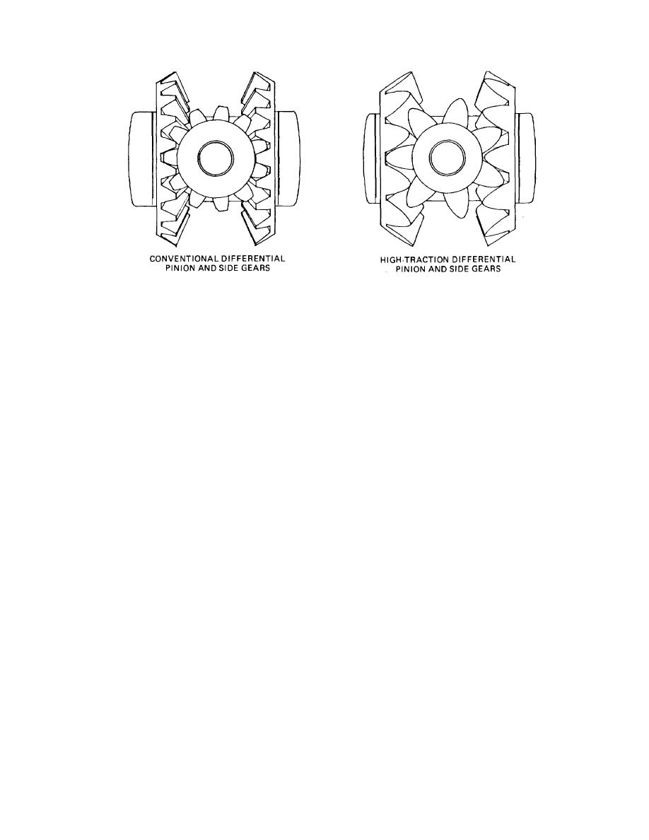
Figure 29-3. Comparison of Conventional and High-Traction Differential Gears.
on one wheel and less on the other as the pinions move
one wheel encounters a slippery spot and loses traction
around, until both wheels start to rotate at the same
while the other wheel is on a firm spot and has traction.
speed. When this occurs, the relative motion between
It will not work, however, when one wheel loses traction
completely. In this respect, it is Inferior to the differential
wheel is again equal. This device assists considerably In
lock.
starting the vehicle or keeping it rolling In cases where
Section II. NO-SPIN DIFFERENTIALS
clutch member remains fully engaged with the spider
29-4. Purpose. To provide a means of improving
clutch teeth. The spider clutch teeth (the driving teeth)
tractive effort at the driving wheels when one wheel
drive the right (inside) wheel at differential drive ring gear
tends to slip from loss of traction, It is necessary that the
speed.
The left wheel (outside) covers a greater
differential prevent actual slippage and supply torque to
distance and must turn faster than differential drive ring
the driving wheels only to the extent that the wheels can
gear speed. The differential must permit this action
utilize the torque without slipping.
The no-spin
because, as the left wheel begins to turn faster, the left-
differential does this by using various types of clutches
driven clutch member also turns faster than differential
between the driving axles.
drive ring gear and spider speed. As the left-driven
clutch member begins to turn faster, the cam lobes or
29-5. Sprag-Type No-Spln Differential (Fig. 29-
ramps on its edge ride up on the cam lobes on the center
4). The sprag-type no-spin differential does not contain
cam. This action pushes the left-driven clutch member
pinion gears and side gears as does the conventional
away from the spider so the clutch teeth disengage. As
differential. Instead, it consists essentially of a spider
the crest of the ramp is passed, spring pressure forces
attached to the differential drive ring gear through four
the teeth of the driven clutch member back Into full
trunnlons, plus two driven clutch members with side
engagement with the teeth on the spider. But the action
teeth that are indexed by spring pressure with side teeth
is repeated as long as the left wheel turns more rapidly
In the spider. Two side members are splined to the
than the right wheel. Full drive is applied to the right
wheel axles and, In turn, are splined into the driven
wheel; no drive is applied to the left wheel. But as soon
clutch members.
as the vehicle completes the turn and the left wheel
slows down to right wheel speed, driving power is applied
a. Operation in Turning. The center
cam in the
equally to
spider is held in place by a snap ring that
permits the
TA233779
center cam to rotate but does not permit
it to move
laterally. When making a right turn, the
right-driven
29-3
|
||
|
||


