
| Tweet |

Custom Search
|
|

|
||
 TM 9-8000
both. For a left turn, the action is similar except that full
other no-spin differential. The teeth are separated so
drive is applied to the left wheel; the right wheel turns
that no driving can take place. In this unit, however, the
more rapidly than the left wheel.
teeth do not index repeatedly because the rotatable cam,
left slightly behind, prevents this. The ramps on the
b. Tractive Effort. With this differential, one wheel
rotatable cam are halfway between the ramps on the
fixed cam of the driven clutch member. The staggered
cannot spin because of loss of tractive effort and thereby
ramps will not permit teeth engagement. As soon as the
deprives the other wheel of driving effort. For example,
turn is completed, the driven clutch member slows down
one wheel is on ice and the other wheel is on dry
to spider speed, the ramps realign, and teeth
pavement. The wheel on ice is assumed to have no
engagement takes place. Where a vehicle has a tandem
traction. However, the wheel on dry pavement will pull to
driving axle unit or multiple axles, a no-spin differential
the limit of its tractional resistance at the pavement. The
may be placed in the transfer case between the output
wheel on ice cannot spin because wheel speed is
shafts to the driving axles. The differential prevents loss
governed by the speed of the wheel applying tractive
of tractive effort from slippage or tractive loss of one set
effort.
of wheels. Also, it tends to balance torque and prevents
interaxle trapped torque, which reduces total tractive
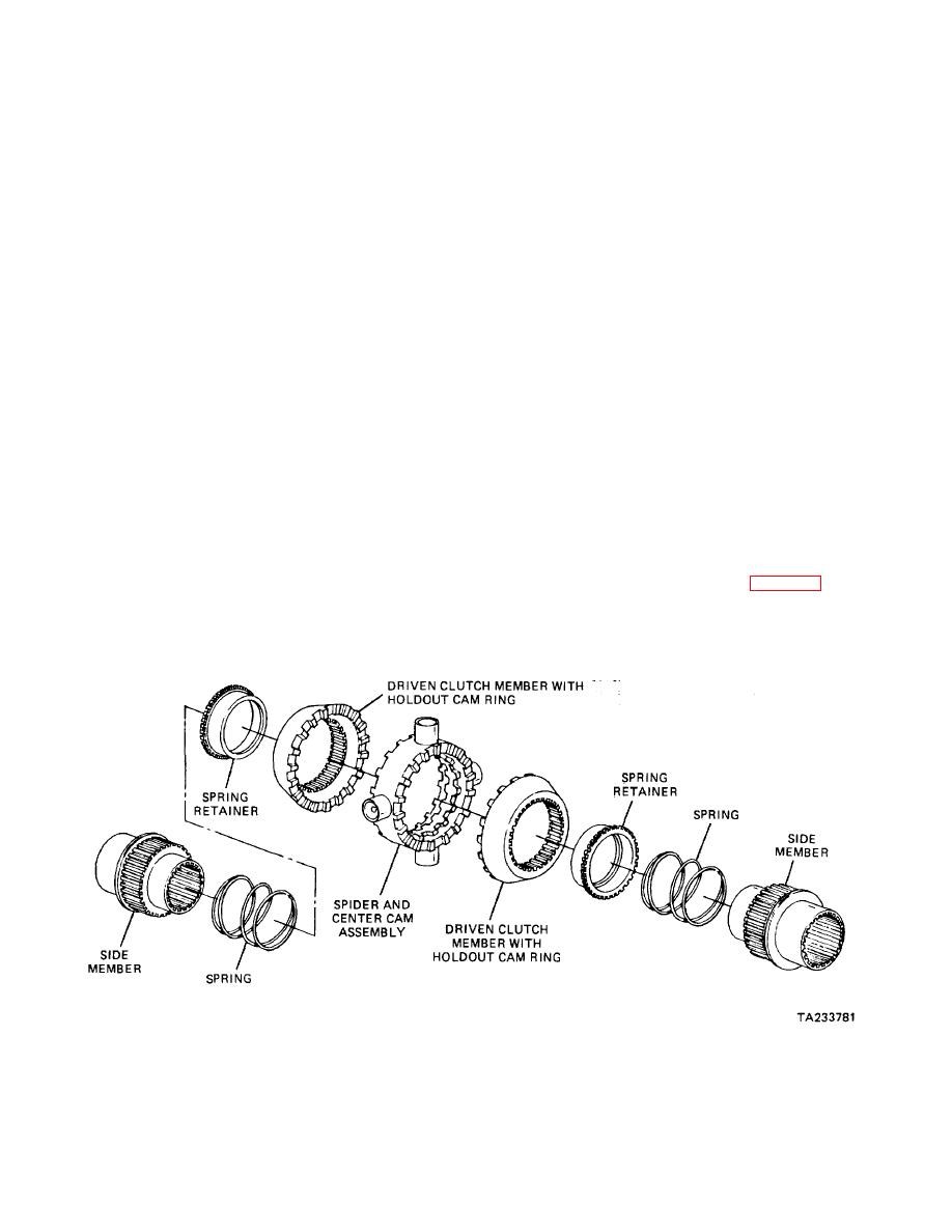
29-6. Silent-Type No-Spin Differential (Fig. 29-
effort.
5). In the silent-type no-spin differential, the construction
is very similar to the unit described above. However, the
29-7.
Clutch-Type No-Spin Differential.
center cam has wider teeth to carry the two sets of cams
in each driven clutch member. One set is fixed, the
other is able to rotate in one direction or the other a few
a. General. The clutch-type no-spin differential
degrees with respect to the fixed set. The rotatable or
holdout cam ring is slotted, and a key in the spider fits
one drive wheel experiences uncontrolled slippage. The
this slot to limit the independent rotation of the cam. The
clutch configurations that are used commonly are the
key also limits the rotation of the center cam. In
cone or the multiple plate type.
operation, when one wheel is turning faster than the
other (as in rounding a turn), the faster-turning splined
b. Multiple Plate Clutch Type (Fig. 29-6). This type
side member and driven clutch member cause the
of no-spin differential uses four side gear pinions on two
ramps on the center cam and driven clutch member cam
shafts that are at right angles to each other. The shafts,
to push the driven clutch member away from the spider.
which are V-shaped on
This action is similar to that described above for the
Figure 29-5. Silent-Type No-Spin Differential.
29-5
|
||
|
||


