
| Tweet |

Custom Search
|
|

|
||
 TM 9-8000
opposite sides of the piston. In the open position, the
frictional resistance which retards the movement of the
valve spool is preloaded by the spring against a hollow
road wheels.
sleeve stop.
b. Construction. The hydromechanical lock-out
system is constructed of the following:
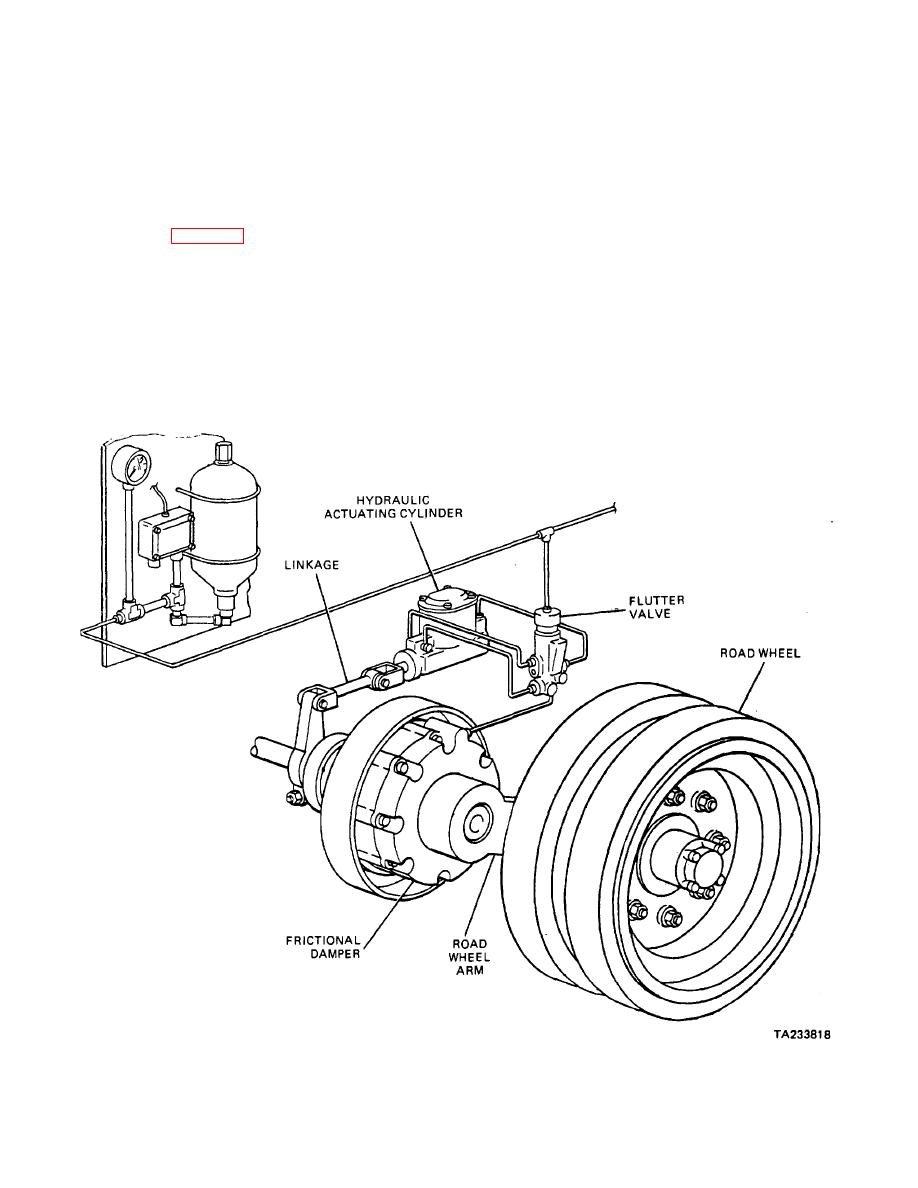
31-10. Hydromechanical Lockout System.
(1) The system uses linkage to connect the
a. Operating Principles. The hydromechanical
road wheel arm to the hydraulic actuating cylinder.
lockout system (fig. 31-5) is a suspension-damping
device that incorporates a suspension lockout. Basically,
(2) The actuating cylinder controls the rate of
the damping device is a frictional damper (disk brake) to
damping the system will produce.
which a hydraulic actuating cylinder is added. The
hydraulic-actuating cylinder or brain box supplies and
(3) The flutter valve directs the pressurized fluid
controls the pressure to the frictional damper where the
to the pistons in the frictional damper.
energy absorption takes place. As the road wheel
moves up or down, the brain box develops pressure
(4) The frictional damper contains the frictional
through the use of a piston rod, which is connected to
plates, which, when compressed, resist the movement of
the road wheel arm through linkage. The pressure
the road wheel arm.
developed is routed to the frictional damper. which
forces the stators and rotors together, creating a
Figure 31-5. Hydromechanical Lockout System.
31-6
|
||
|
||


