
| Tweet |

Custom Search
|
|

|
||
 TM 9-8000
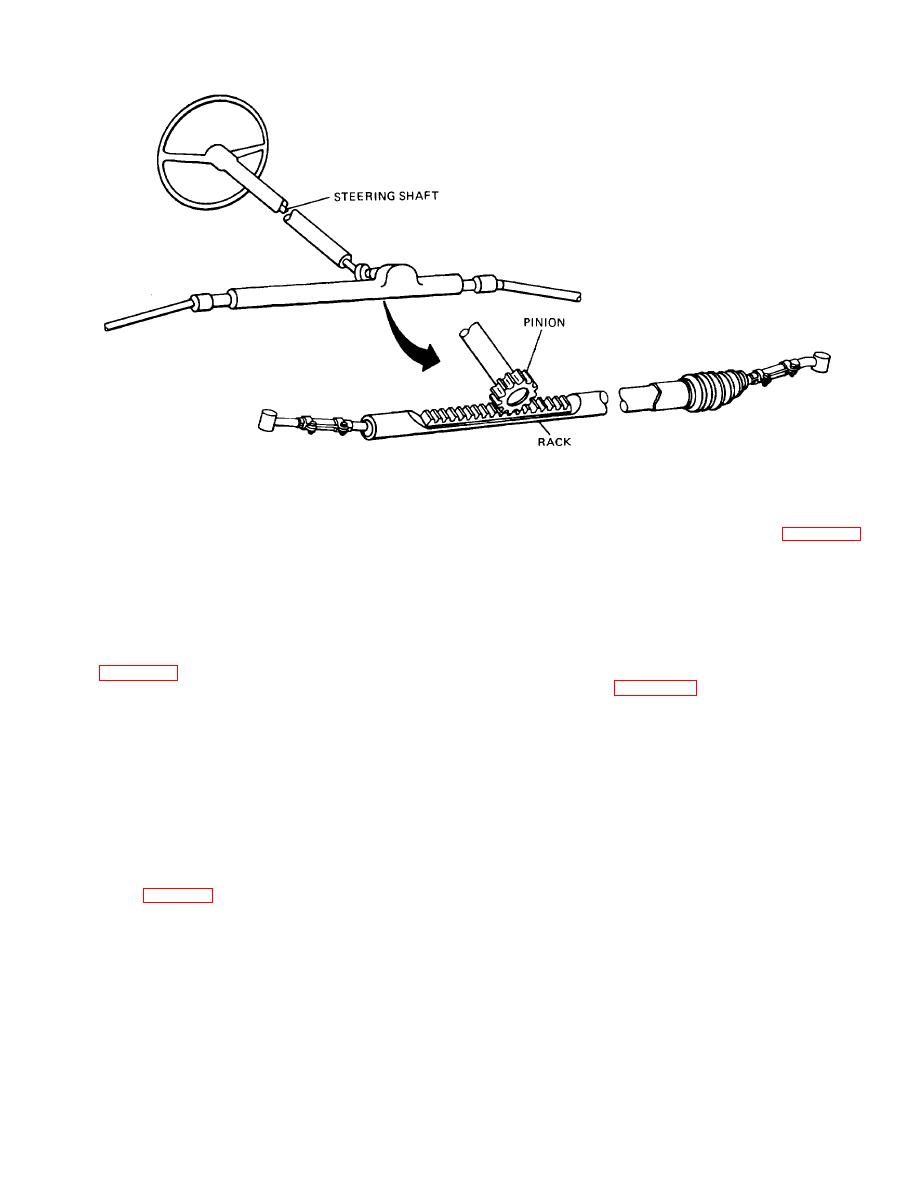
Figure 33-11. Rack and Pinion Steering Gear
Section III. POWER STEERING - HYDRAULIC TYPE
c. Control Valve. The control valve (fig. 33-13),
33-9. Purpose. The power steering system is designed
which is actuated by the steering wheel movements, is
to reduce the effort required to turn the steering wheel.
designed to direct the hydraulic fluid under pressure to
This task is accomplished by an auxiliary power network
the proper location in the steering system. The control
incorporated in the steering system.
valve may be mounted either in the steering box or on
the steering linkage, depending on which system
33-10. Components.
configuration is being used.
a. Pump. All power steering systems contain a
d. Gearbox. The gearbox used in an integral power
pump (fig. 33-12) that supplies hydraulic fluid under
steering system (fig. 33-14) is basically a manual
pressure to the other components in the system. The
gearbox that is adapted to include a power assist
pump, which may be of the gear teeth, rotor, or vane
package. The integral power steering gearbox are of two
type, usually is driven by the engine by means of a V-belt
types: offset and in line. The offset type utilizes a
and is functional whenever the engine is operating.
recirculating ball-type gear-box with a rack meshed to the
Some models mount the pump in front of the engine and
pitman sector gear above or on the opposite side of the
are driven directly by the crankshaft. The pressure and
ball nut. The power steering force is developed in the
flow relief valves are always built into the pump. These
power piston, which is offset from the worm and nut and
valves are designed to limit the amount of pressure and
attached to the rack. The in-line design uses the
flow the pump develops throughout the different engine
recirculating ball nut assembly as a power piston. In this
speeds.
design, the ball nut is sealed inside a cylindrical portion of
the steering gear housing. The power steering effect is
b. Reservoir. The pump receives its oil supply from
produced by alternately pressurizing either side of the
the reservoir (fig. 33-12), which usually is an integral part
power piston.
of the pump. Power steering fluid is generally added to
the system and checked atthe reservoir.
e. Hydraulic Cylinder. The hydraulic cylinder that is
used on the semi-integral and integral
TA233841
33-8
|
||
|
||


