
| Tweet |

Custom Search
|
|

|
||
 TM 9-8000
b. Check Valve. A combination inlet and outlet check
valve (fig. 34-21) is in the head of the master cylinder,
held in place by the piston return spring. The check valve
consists of a rubber valve cup In a steel valve case. This
assembly rests on a rubber valve seat that fits in the end
of the cylinder. In some designs, the check valve
consists of a spring-operated outlet valve seated on a
valve cage, rather than a rubber-cup outlet valve. The
principle of operation is the same. The piston return
spring normally holds the valve cage against the rubber
valve seat to seal the brake fluid in the brake line.
hydraulically. The individual brake systems may be
designed to divide the system front to rear, diagonally, or
in various other fashions. If a brake fluid leak develops in
one circuit, the other circuit still provides emergency
stopping capability. As the brake pedal Is depressed
under normal operating conditions, it forces the primary
piston forward to cover the primary compensating port.
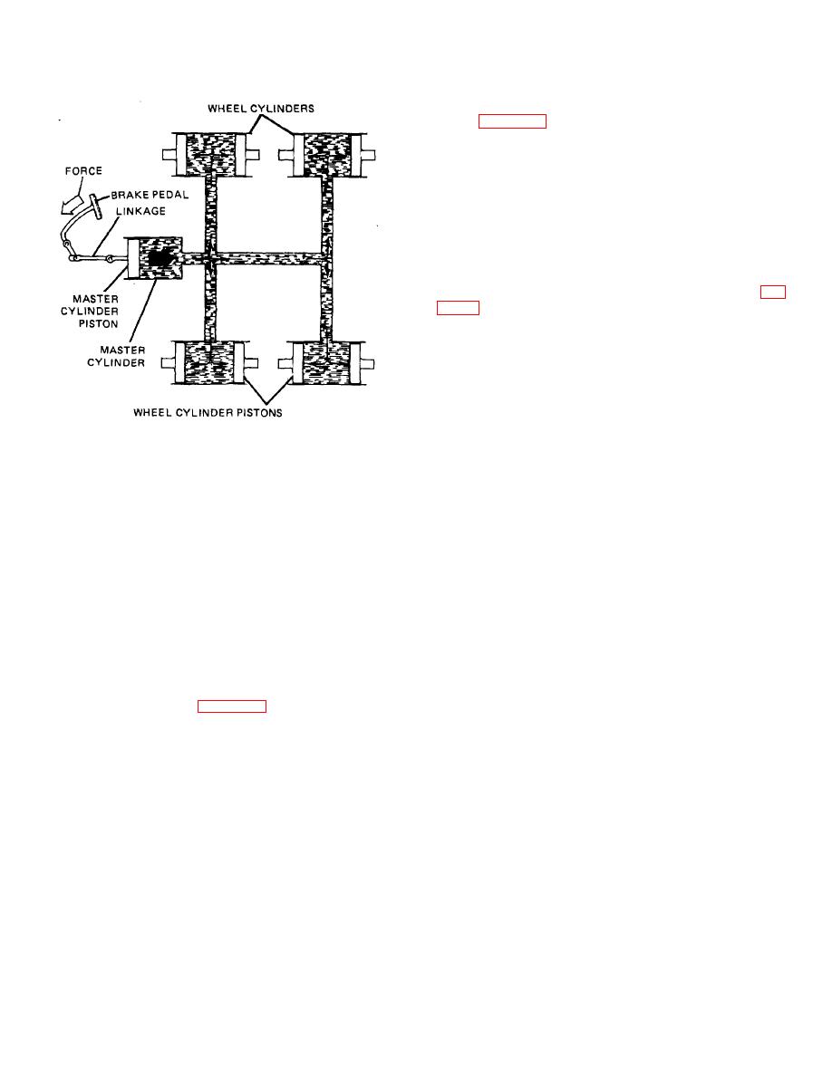
Figure 34-20. Diagram of Hydraulic
At this time, the primary chamber is sealed and direct
Brake System.
hydraulic pressure is transmitted to the secondary piston.
As the brake pedal continues to travel, the secondary
34-25. Master Cylinder. The master cylinder is the
piston covers the compensating port. Further application
primary unit in the brake system that converts the force
of the brake pedal develops the pressure required to
of the driver's foot into fluid pressure to operate the
apply the brake components. Should a leak develop in
wheel brake cylinders. The master cylinder housing is an
the primary circuit, the brake system would not be
aluminum or iron casting that may have an integral
rendered useless. During the application of the brakes,
reservoir, in which case, it usually is made of the same
the primary piston would continue to move forward,
material the cylinder is made of, or a detachable nylon or
unable to build pressure due to the malfunction.
steel reservoir. The reservoir carries sufficient reserve
Approximately halfway through its maximum stroke, the
fluid to allow for expansion and contraction of brake fluid
primary piston contacts the secondary piston. Further
and brake lining wear. The reservoir is filled at the top
application of the brake would force the secondary piston
and is well sealed by a removable filler cap containing a
forward to develop pressure In the secondary system,
vent. The master cylinder usually is mounted to the
which would allow for braking action to take place In two
firewall, which allows for easy Inspection and service
wheels. Should the secondary circuit fail, braking for the
and is less prone to dirt and water.
other two wheels would still be available. The primary
piston would move forward and cover the primary
a. Piston. The piston (fig. 34-21) is a long, spool-like
compensating port as before. Because of the rupture in
member with a rubber secondary cup seal at the outer
the secondary circuit, the secondary or floating piston
end and a rubber primary cup that acts against the brake
would be moved to its extreme stop by the force of the
liquid just ahead of the Inner end. This primary cup is
return spring. Further application of the brake would
kept against the end of the piston by a return spring. A
develop enough pressure in the primary circuit to apply
steel stop disk, held in the outer end of the cylinder by a
the brakes connected to this circuit, therefore allowing
retainer spring, acts as a piston stop. A rubber boot
the vehicle to maintain some stopping ability.
covers the piston end of the master cylinder to prevent
TA233872
dust and other foreign matter from entering it. This boot
is vented to prevent air from being compressed within it.
34-25
|
||
|
||


