
| Tweet |

Custom Search
|
|

|
||
 TM 9-8000
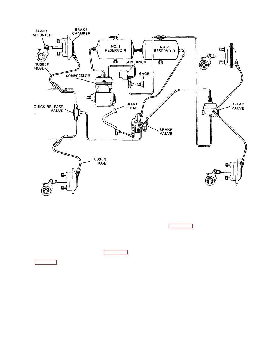
Figure 34-31. Typical Airbrake System.
compressed. The pressure developed lifts the discharge
34-39. System Components.
valve and the compressed air is discharged to the
reservoirs (fig. 34-32). The discharge valve closes as
a. Air Compressor. Air compressors usually are
soon as pressure Is relieved when the piston starts its
single-acting reciprocating units, either self-lubricated
downstroke.
or lubricated from the vehicle engine lubricating system.
Both water-cooled and air-cooled cylinder heads are
used. Compressors having a displacement of
b. Unloader. When the reservoir air pressure reaches
approximately 7 cfm have two cylinders (fig. 34-32),
the maximum setting of the governor, air under pressure
while those with a displacement of 12 cfm have three
is allowed by the governor to pass into a cavity below an
cylinders (fig. 34-33).
unloading diaphragm in the cylinder head. This air
pressure lifts one end of the unloading lever, which
The air compressors operate continuously while the
pivots on its pin and forces the unloading valves off their
engine is running, but the actual compression of air is
seats. With the unloading valves off their seats, the
controlled by the governor.
unloading cavity forms a passage between the cylinders
above the pistons. Air then passes back and forth
With a partial vacuum created on the piston downstroke,
through the cavity between the cylinders and
intake ports are uncovered near the bottom of the stroke.
compression is stopped. A drop in air pressure below the
Intake ports are covered as the piston starts its upstroke.
minimum setting of the governor causes
Air in the cylinder is
TA233880
34-34
|
||
|
||


