
| Tweet |

Custom Search
|
|

|
||
 TM 9-8000
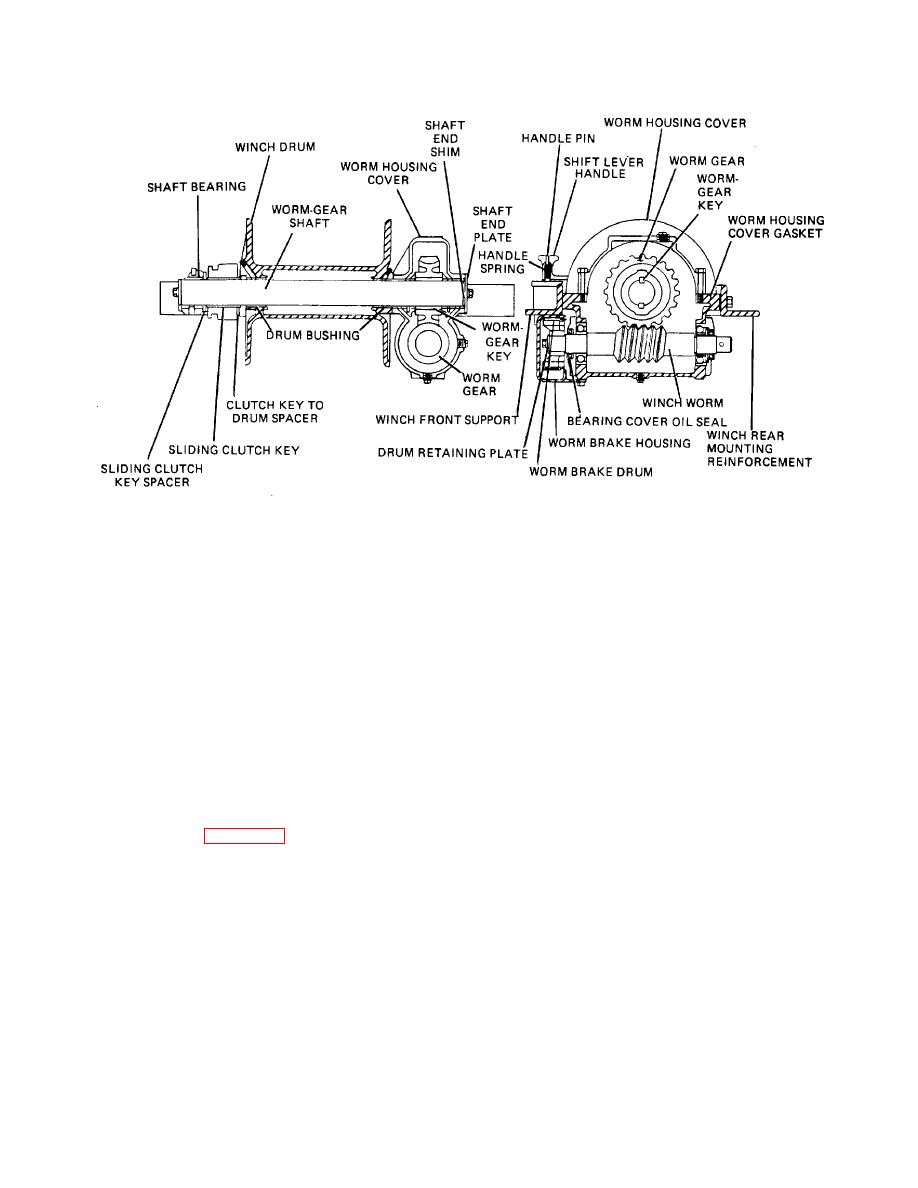
Figure 36-6. Jaw-Clutch Worm-Gear Winch.
cable due to loose crossed coils and layers, and it allows
36-10. Level Wind Winches. Some winches may be
off leads of the cable while maintaining level winding.
equipped with an automatic level winding device to spool
the cable on the drum in tight, even coils and layers.
This prevents crushing of the
Section III. TIRE INFLATION SYSTEM
attained and automatically starts the pump when
36-11. Purpose. Amphibious trucks are equipped with
pressure in the tank drops below a prescribed limit. Air
a central' tire-pressure control system, by means of
pressure is piped from the tank to the inflation and
which the tires may be inflated or deflated to meet
deflation control valves assembly.
various conditions encountered by the vehicle. When
operating on sand, the tires are deflated to obtain
When the control valve lever is placed in the INFLATE
adequate flotation; to travel on a hard surface, the tires
position, air passes through the valve to the air line
are inflated.
manifold and valves, then to each tire, and through
individual air lines and tire inflating devices. A safety
36-12. Construction. Location of each component of
valve is located in the system. The tire-inflating device, or
the system is shown in figure 36-7. A two cylinder,
hub device, is mounted on each wheel hub. It is an
water-cooled, self-lubricated pump with a capacity of 9
airtight rotary joint that provides a connection between
cfm is mounted in the front compartment and driven
the air supply line and the tire. The inner part rotates
directly by the engine crankshaft. This maintains
with the wheel hub while the outer part is held stationary
pressure in the air tank. It is controlled by a governor
by a swivel-ended strut attached to the hull.
that stops the pump when maximum allowable pressure
is
TA233898
36-5
|
||
|
||


