
| Tweet |

Custom Search
|
|

|
||
 TM 9-8000
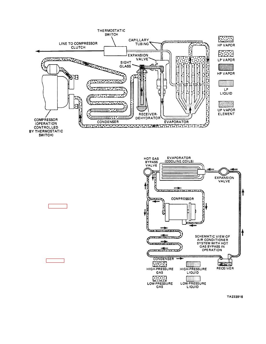
Figure 37-6. Thermostatic Evaporator.
engage and disengage the compressor. The switch is
operated by a sensing bulb placed in the airstream after
the evaporator. As the evaporator temperature falls, the
thermostatic switch opens to disengage the magnetic
clutch in the compressor. When the coil temperature
reaches the proper level, the switch again closes to
engage the clutch and again drive the compressor.
b. Hot Gas Bypass Valve. The hot gas bypass
valve was used on some older models to control
evaporator icing (fig. 37-7). The valve is mounted on
the outlet side of the evaporator. The high-pressure gas
from the compressor Joins with the low-pressure gas
exiting the evaporator. These two gases mix, causing a
pressure increase. The boiling point also increases,
resulting in a loss of cooling efficiency. This, in turn,
causes the evaporator temperature to increase, thus
eliminating freezeup. The compressor is designed to run
constantly (when it is activated) in the hot gas bypass
valve system.
c. Suction Throttling Valve. The suction
throttling valve (fig. 37-8) is used now in place of the hot
gas bypass valve system. It is placed in line with the
outlet of the evaporator. This system is designed to limit
the amount of low-pressure vapor entering the
compressor. The suction throttling valve operates as
follows:
Figure 37-7. Hot Gas Bypass Valve.
37-7
|
||
|
||


