
| Tweet |

Custom Search
|
|

|
||
 3500 ENGINE
SPECIFICATIONS
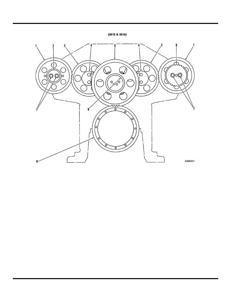
REAR GEAR GROUP
(1)
Camshaft drive gears.
d.
Tighten bolts (7) in steps to a torque of
(2)
Plate.
of
100 15 N-m (75 + 11 lb. ft.)
(3)
Camshaft idler gears.
e. Hit the face of plate (2) or drive gear (6),
(4)
Diameter of shafts
then tighten the bolts to a torque
(new) 74.900 + 0.015 mm (2.9488 + .0006 in )
of
100 f 15 N-m (75 11 lb. ft.)
Bore in bearings (after
f.
Again hit the face of plate (2) or drive gear
assembly) ..................................75.000 0.055
(6) and again tighten the bolts to a
mm (2.9528 + 0022 in.)
torque of ............................ 100 15 N-m
(5)
Cluster idler gear.
(75 + 11 lb. ft.)
(6)
Gear for hydramechanical protective system
NOTE: If necessary, repeat Step 7f until the bolts hold
drive.
(7)
Bolts. Tighten the bolts as follows:
are in full contact with the taper on the camshafts.
a. Put camshaft drive gears (1) in position on
the camshafts.
(8)
Diameter of shaft
b. Use hand pressure to turn and hold
(new)
74.900 + 0.015 mm (2.9488 + 0006
camshaft drive gears (1) in their normal
in )
direction of rotation. This removes all gear
Bore in bearing (after
clearance (backlash) between camshaft
assembly) .................................. 75 000 + 0 053
mm (2 9528 t .0021 in )
(3).
(9)
Crankshaft gear.
c. Install plate (2) (on left side of engine)
and/or drive gear (6) (on right side of
engine) to hold camshaft drive gears (1) to
each camshaft.
46
|
||
|
||


